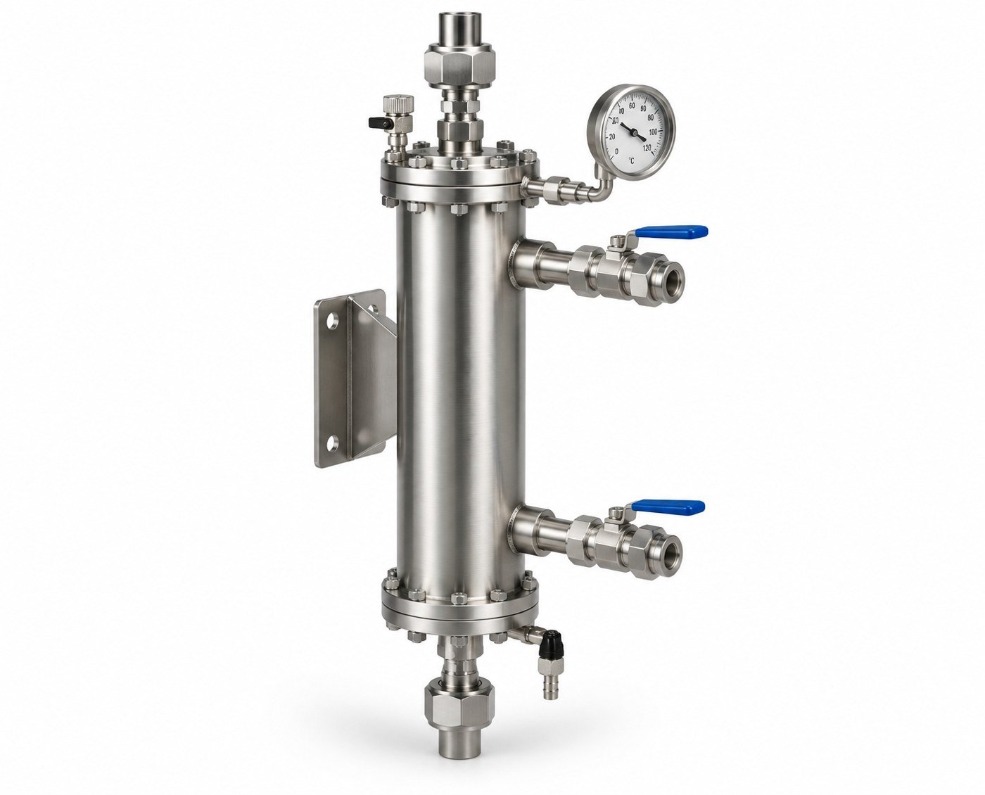
Description
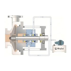
API Plan 23 is an engineered seal flush arrangement that circulates process fluid from the seal chamber through an internal pumping ring, passes it through a heat exchanger, and returns the cooled fluid back to the seal chamber.
This localized closed-loop circulation reduces heat load at the seal faces while limiting direct mixing between hot pumpage and cooled seal chamber fluid.
The system is particularly suited for hot water, boiler feed water, hot hydrocarbons, and clean non-polymerizing fluids where vapor pressure margin, lubricity, and thermal stability are critical. Compared with direct-discharge cooling arrangements, Plan 23 provides efficient seal cooling with reduced cooler duty, lower cooling water demand, and reduced risk of heat exchanger fouling.
Key Features
- · Improves vapor pressure margin and helps reduce flashing risk at the seal faces.
- · Compact cooler duty reduces heat exchanger size and cooling water consumption.
- · Enhances hot water lubricity and seal face film stability in high-temperature service.
- · Vent and drain provisions support commissioning, air removal, and safe maintenance.
- · Closed-loop recirculation using an internal pumping ring for controlled seal chamber cooling.
- · Recommended with close-clearance throat or restriction bushing to reduce hot product mixing.
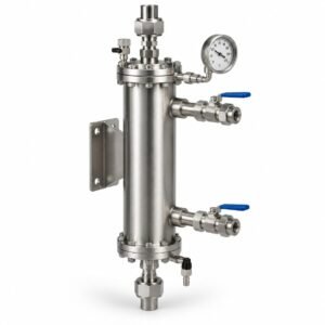
- · Heat exchanger removes localized seal heat without continuously cooling the full process stream.
Service Overview
| Parameter | Value |
|---|---|
| Equipment | Centrifugal pumps with single mechanical seals |
| Fluid | Hot hydrocarbons, boiler feed water, hot water, clean non-polymerizing fluids |
| Service Nature | High-temperature, hot/volatile, clean process fluid service |
| Operating Mode | Closed-loop seal chamber recirculation through a heat exchanger |
| Typical Arrangement | API Plan 23 with pumping ring, cooler, temperature indicator, vent, drain, and optional quench |
Specifications
| Item | Min | Max | Typical / Notes |
|---|---|---|---|
| Size | On Request | On Request | Selected to suit seal size, gland connections, pump geometry, and circulation flow |
| Pressure | — | 62 bar (899 psi) | System pressure rating |
| Temp | Ambient / process-dependent | +180°C (+356°F) | Maximum listed service temperature; cooler duty depends on seal heat load |
| Speed | On Request | On Request | Governed by mechanical seal design, pumping ring geometry, shaft speed, and circulation requirement |
| Heat Removal Capacity | — | 10.5 kW (35,826 BTU/hr) | Rated heat removal capacity |
| Cooling Medium | — | On Request | Typically, cooling water is passed through a shell/coil heat exchanger |
Materials
| Component | Standard Material | Optional Material | Comment |
|---|---|---|---|
| Heat Exchanger Coil | SS 316 | Duplex SS / Hastelloy / Titanium | Selected for process compatibility and chloride/corrosion exposure |
| Heat Exchanger Shell | Carbon Steel / Stainless Steel | SS 316 / Duplex SS | Based on the cooling water quality and the site metallurgy standard |
| Piping & Fittings | SS 316 | CS / SS 304 / Alloy materials | SS 316 preferred for hot water and hydrocarbon service |
| Pumping Ring | Seal OEM standard material | SS 316 / Duplex SS / Alloy materials | Geometry must match the seal chamber circulation requirement |
| Instrumentation | Temperature Indicator | Temperature Transmitter / Switch | Used for monitoring the cooler outlet or seal chamber loop temperature |
| Vent & Drain Valves | SS 316 / CS | Alloy construction | Normally closed; required for commissioning and maintenance |
Applications
- · Clean, non-polymerizing chemical process fluids.
- · Hot water circulation pumps in thermal/process systems.
- · Hot hydrocarbon pumps in refinery and petrochemical service.
- · Boiler feed water pumps in power generation and utility service.
- · High-temperature pump services requiring improved vapor margin.
- · Single mechanical seal installations with localized seal chamber cooling.
- · Services where reduced cooling water usage and lower heat exchanger fouling are required.
Operating Limits
| Parameter | Value |
|---|---|
| Pressure | Up to 62 bar (899 psi) |
| Temp | Up to +180°C (+356°F) |
| Speed | On Request; dependent on seal and pumping ring design |
| Size Range | On Request; configured to suit seal chamber, gland, and connection size |
| Heat Removal Capacity | Up to 10.5 kW (35,826 BTU/hr) |
| Recommended Service | Hot water, boiler feed water, hot hydrocarbons, clean non-polymerizing fluids |
API Plan 23 – Frequently Asked Questions
What is the difference between API Plan 21 and API Plan 23?
Both plans cool the seal chamber with a heat exchanger. Plan 21 takes product from the pump discharge, through a restriction orifice and cooler, into the seal chamber, so the cooler continuously cools a flush stream that then returns to the process. Plan 23 recirculates only the seal-chamber fluid in a closed loop driven by a pumping ring, so the cooler removes seal-generated heat instead of cooling product. The result is lower cooler duty, lower cooling-water demand and less heat-exchanger fouling.
When should API Plan 23 be selected?
For hot water, boiler feed water, hot hydrocarbons and clean, non-polymerizing fluids where the seal-chamber temperature must be lowered to improve vapour-pressure margin and fluid-film stability at the seal faces. A close-clearance throat or restriction bushing is recommended to limit mixing with the hot pumpage.
What instrumentation does a Plan 23 loop normally include?
A temperature indicator on the cooler outlet or seal-chamber loop, a high-point vent for air removal during commissioning, and a low-point drain for maintenance. A temperature transmitter or switch can be added for remote monitoring.
Related API 682 Seal Support Systems