


Description;
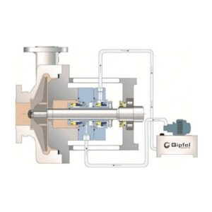
API Plan 53A is a pressurized seal support system that supplies clean barrier liquid from an external reservoir to the cavity of a dual pressurized mechanical seal. The reservoir is charged with an inert gas—typically nitrogen or clean instrument air—to maintain the barrier fluid at a pressure higher than the seal‑chamber pressure, ensuring that any leakage across the inboard seal is barrier fluid flowing toward the process rather than process media escaping to the atmosphere. Circulation of the barrier liquid between the seal and reservoir is achieved by a pumping ring during operation and may be supplemented by thermosiphon circulation when the equipment is stopped.
Plan 53A is selected when the process fluid is volatile, hazardous, toxic, dirty, abrasive, or polymerizing, or otherwise unsuitable as a lubricant for the inboard seal faces. Because barrier pressure is intentionally higher than process pressure, a small, controlled amount of barrier liquid enters the process, so the application must tolerate limited product dilution, and the barrier fluid must be compatible with the process.
The pressurized reservoir provides a defined buffer volume where wear particles can settle at the bottom instead of recirculating through the seal, and it can be sized according to the required circulation rate and operating duration.
Heat generated at the seal is removed via a cooling coil inside the reservoir or through an external air or water cooler, helping to maintain stable barrier‑fluid temperature and seal reliability.
Changes in reservoir pressure and level provide straightforward condition monitoring: a rise in pressure or level typically indicates an increase in inboard seal leakage, while a drop in level indicates loss of barrier liquid due to inboard and/or outboard leakage. TS‑type vessels are supplied with all necessary process and instrumentation connections and mounting brackets, and their modular design allows integration of accessories such as level switches or transmitters, pressure gauges, pressure transmitters, circulation or refill pumps, thermometers, drain and vent valves, and base frames to meet specific site safety, monitoring, and maintenance requirements.
Key features and advantages;
- Compatible with pumping-ring circulation, providing reliable heat removal without an external circulation pump.
- Barrier fluid must be clean, compatible, and lubricating to protect the inboard seal faces and support long service life.
- Supports hazardous and toxic services by directing leakage toward the process side rather than to the atmosphere.
- Instrumentation-ready design with provision for pressure and level alarms enables early detection of seal or system upset.
- Reservoir can be dismantled for cleaning, allowing simple inspection and optimum maintenance of the vessel interior.
- Suitable for services where controlled product dilution is acceptable, while maintaining sealing reliability and process safety.
- Designed for use with pressurized dual seals, providing reliable containment and stable face lubrication in demanding services.
- Suitable for demanding operating conditions up to 30 bar and 200 °C, making it appropriate for severe process environments.
- Clean barrier fluid is supplied to the inboard seal faces, improving lubrication, reducing wear, and supporting safe operation.
- Internal circulating device ensures continuous barrier-liquid movement, helping remove heat and maintain stable operating conditions.
- Integrated cooling coil dissipates heat from the barrier fluid and helps maintain viscosity and thermal stability during continuous duty.
- External reservoir provides level indication, make-up volume, and pressure-source connection, supporting easy monitoring and system control.
- Gland inlet and outlet connections are arranged according to shaft rotation, ensuring correct circulation direction and proper system performance.
- Barrier fluid maintained at 1–2 bar(g) above maximum seal-chamber pressure to ensure positive pressure differential and controlled leakage management.
- Constructed from 1.4571 stainless steel with borosilicate sight glasses, offering broad corrosion resistance and suitability for universal industrial applications.
- Fluid circulation is maintained by a pumping ring integrated into the dual-seal assembly, eliminating the need for a separate circulation pump in standard operation.
Service Overview;
| Parameter | Value |
| Equipment | Dual pressurized mechanical seals on centrifugal pumps, mixers, agitators, and vacuum-rated rotating equipment. |
| Fluid | Clean compatible barrier liquid; applicable to high vapour pressure fluids, light hydrocarbons, hazardous/toxic media, dirty or polymerizing process streams. |
| Service Nature | Pressurized barrier-fluid system where controlled barrier leakage into the process is acceptable, and process liquid is unsuitable for seal-face lubrication. |
| Operating Mode | Continuous circulation by seal pumping ring or thermosiphon; reservoir maintained above seal-chamber pressure with nitrogen or clean instrument air. |
Specifications;
| Item | Min | Max | Typical/Notes |
| Shaft Size | 20 mm (0.75”) | 150 mm (6.00”) | Seal-dependent; larger sizes available by engineered design. |
| Barrier Pressure | Seal chamber +1.4 bar (+20 psi) | 17 bar (250 psi) | Maintain above maximum seal-chamber pressure; reservoir MAWP is project-specific. |
| Temperature | -40°C (-40°F) | +200°C (+392°F) | Limited by barrier fluid, elastomers, instruments, and cooling-coil duty. |
| Speed | 0 m/s (0 ft/min) | 23 m/s (4,500 ft/min) | Peripheral speed at seal faces; verify with selected dual seal design. |
Materials;
| Component | Standard Material | Optional Material | Comment |
| Reservoir Shell | 316/316L stainless steel | Carbon steel, duplex SS, alloy construction | ASME/API package rating to be confirmed per project. |
| Tubing / Piping | 316 stainless steels | Monel®, Hastelloy® C-276, duplex SS | Sized to minimize pressure drop and support stable circulation. |
| Cooling Coil | 316 stainless steels | Duplex SS, alloy coil | Recommended where barrier-fluid heat load is significant. |
| Instrumentation | SS pressure gauge, level gauge, pressure/level switches | Transmitters, alarms, local panel, remote monitoring | Use hazardous-area ratings where required. |
| Valves / Fittings | 316 SS needle, block, check, and drain valves | Double-block, DBB, high-pressure fittings | Configuration per plant piping class. |
| Seal Materials | SiC/Carbon or SiC/SiC faces; FKM elastomers | TC, FFKM, EPDM, AFLAS®, PTFE | Selected to process, temperature, and barrier-fluid compatibility. |
Applications;
- Mixers, agitators, reactors, and vacuum services requiring positive barrier pressure.
- Heat-transfer fluids where seal-face cooling and controlled barrier dilution are acceptable.
- Refinery and petrochemical light hydrocarbon services, including high-vapor-pressure fluids.
- Hazardous, toxic, odorous, or environmentally sensitive chemical services requiring containment.
- Dirty, abrasive, crystallizing, or polymerizing fluids that cannot reliably lubricate the inboard seal faces.
- Pump services where product leakage to the atmosphere must be minimized by a pressurized dual-seal
arrangement.
Operating Limits;
| Parameter | Value |
| Barrier Pressure | Typically, seal chamber +1.4 bar (+20 psi) minimum; up to 17 bar (250 psi) standard package range. |
| Temperature | -40°C to +200°C (-40°F to +392°F), subject to elastomers, barrier liquid, and instrumentation limits. |
| Speed | Up to 23 m/s (4,500 ft/min) peripheral speed, subject to selection due to the mechanical seal design. |
| Size Range | 20–150 mm (0.75–6.00”) shaft size typical; engineered sizes available. |
Engineering note;
Values are preliminary industry-standard defaults. Verify final limits against selected seal, reservoir MAWP, barrier-fluid vapour pressure, elastomers, instrumentation, piping class, and applicable API 682 / project specifications.

Reviews
There are no reviews yet.