
Description;
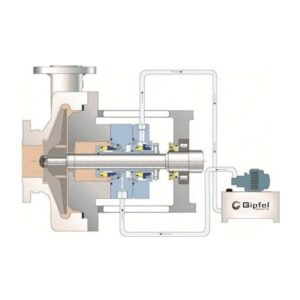
API Plan 52 is an external buffer-fluid reservoir system designed for unpressurized dual- or tandem-mechanical-seal arrangements. The system supplies clean, compatible buffer fluid to the outer seal while circulation is typically induced by a pumping ring within the seal assembly. A reservoir with a sight level gauge, cooling coil, fill connection, drain, vent-to-collection connection, and optional pressure or level instrumentation supports thermal control, leakage indication, and safer containment of volatile or hazardous process fluids.
In service, the buffer fluid is maintained below seal chamber pressure, making Plan 52 suitable where product dilution by a pressurized barrier fluid is not acceptable. It is commonly selected for high vapor pressure fluids, flashing light hydrocarbons, hazardous or environmentally sensitive liquids, toxic fluids, and heat transfer fluids. Proper installation requires self-venting piping, low-resistance tubing runs, reservoir elevation above the seal, and continuous venting to a safe collection or flare system where required.
Technical Key Features;
- Integrated cooling coil removes heat from the circulating buffer fluid and supports stable operating temperature in the seal support loop.
- Flow induction: Fluid circulation is driven by the seal’s pumping ring, ensuring effective movement of buffer fluid through the reservoir and seal gland.
- Sight‑level gauge and optional level transmitter enable visual level indication and remote monitoring for leakage trending and maintenance planning.
- Cooling mechanism: Integrated cooling coils promote heat removal from the buffer fluid, preventing overheating and helping maintain seal reliability.
- Vent‑to‑collection connection allows vapour or leakage from the reservoir to be routed to a safe drain or recovery system, improving environmental control.
- Buffer fluid management: The reservoir ensures a consistent supply of buffer fluid to the outer seal, improving reliability of unpressurized dual‑seal arrangements.
- Safety backup: The outboard seal functions as a containment seal, providing redundancy and additional protection if the inboard seal performance degrades.
- Pumping‑ring circulation maintains continuous flow between the mechanical seal and the reservoir, either by thermo‑siphon effect or forced circulation, depending on system design.
- Thermo‑siphon or forced circulation: Fluid exchange can occur via natural convection (thermo‑siphon) or by a small circulation pump, providing flexible thermal‑management options.
- Installation elevation: The TS vessel must be installed higher than the mechanical seal so that buffer/barrier fluid can return to the vessel through the return line, enabling proper thermo‑siphon circulation.
- External reservoir provides stable buffer‑fluid management for unpressurized dual seals, keeping the buffer fluid at a pressure below the seal‑chamber pressure to reduce the risk of process contamination.
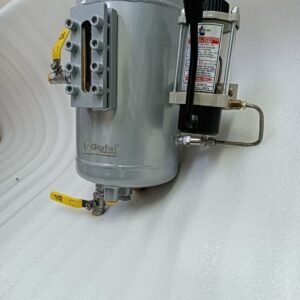
- Modular D‑AP52 system design: Supplied with all standard process and instrumentation connections and mounting brackets, the vessel supports a full range of modular accessories—including pressure gauge, pressure transmitter, level switch/level transmitter, thermometer, refill or circulation pump, drain valves, base frame, and other site‑specific components—allowing the seal support system to be configured precisely to plant safety, monitoring, and maintenance requirements.
Service Overview;
| Parameter | Value |
| Equipment | Centrifugal pumps, process pumps, hydrocarbon transfer pumps, heat transfer fluid pumps, refinery and chemical process rotating equipment |
| Fluid | High vapor pressure fluids, light hydrocarbons, hazardous liquids, toxic media, heat transfer fluids, and clean non-polymerizing services |
| Service Nature | Volatile, flashing, environmentally sensitive, hazardous, or services requiring dual-seal containment |
| Operating Mode | Continuous circulation by pumping ring, thermosiphon effect, or forced circulation, depending on seal and system configuration |
Specifications;
| Item | Min | Max | Typical/Notes |
| Size | On Request | On Request | Typical reservoir volume 10 L (2.64 gal); custom vessel sizes and connection layouts available |
| Pressure | Buffer fluid below seal chamber pressure | Vessel designs up to 32 bar (464 psi) | Plan 52 is an unpressurized buffer system; buffer pressure is typically kept below seal chamber pressure and below 2.8 bar (40 psi) where applicable |
| Temp | -20°C (-4°F) | +400°C (+752°F) | Final rating depends on vessel design, cooling duty, buffer fluid, gasket, instrumentation, and metallurgy |
| Speed | — | Seal dependent | No independent Plan 52 speed limit; circulation depends on seal pumping ring design, shaft speed, buffer-fluid viscosity, and piping resistance |
Materials;
| Component | Standard Material | Optional Material | Comment |
| Reservoir / Shell | Carbon Steel / SS 316 | SS 304, SS 316L, 1.4571, Duplex SS | Selected by pressure rating, corrosion allowance, and site specification |
| Cooling Coil | SS 316 | SS 316L, Duplex SS, Alloy 625 | Used for buffer-fluid heat removal |
| Sight Glass | Borosilicate Glass | Reflex / Transparent level gauge assembly | For visual level monitoring |
| Tubing / Manifold / Valves | SS 316 | CS, SS 316L, Duplex SS, Hastelloy | Based on fluid compatibility and plant piping class |
| Gaskets / Seals | PTFE | FKM, Graphite, spiral-wound gasket | Temperature and chemical compatibility to be verified |
Applications;
- Heat transfer fluid circulation systems.
- Refinery light hydrocarbon pump services.
- Petrochemical high-vapor-pressure fluid transfer.
- Chemical process pumps handling hazardous or toxic liquids.
- Volatile organic compound service requiring controlled collection.
- Environmentally sensitive services requiring leakage containment and monitoring.
- Dual mechanical seal systems where product contamination by barrier fluid is not acceptable.
Operating Limits;
| Parameter | Value |
| Pressure | Vessel designs up to 32 bar (464 psi); buffer fluid maintained below seal chamber pressure |
| Temp | -20°C to +400°C (-4°F to +752°F), design dependent |
| Speed | Seal and pumping-ring dependent; confirm with seal selection |
| Size Range | Reservoir volume and connection sizes on request; 10 L (2.64 gal) typical reference configuration |
Selection Note;
Operating limits above are based on the provided API Plan 52 data and standard Plan 52 engineering practice. Final values should be verified against the selected vessel code, seal arrangement, process pressure, buffer fluid, cooling-water availability, instrumentation philosophy, and site piping specification.

Reviews
There are no reviews yet.