
Mining & Mineral Processing
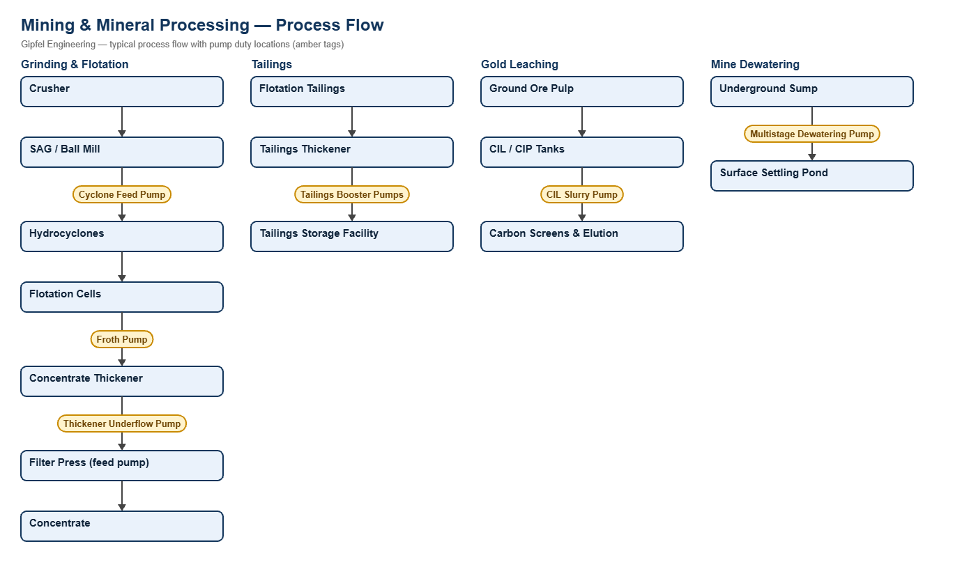
Process Overview
Mining & Mineral Processing — Process Overview
Mineral processing plants pump some of the most abrasive fluids in industry: dense ore slurries above 60% solids carrying hard quartz, silica and pyrite particles, aerated flotation froth, thick thickener underflows and long-distance tailings. Slurry seals must keep particles out of the faces, keep springs out of the product, and tolerate shaft deflection.
Primary Processing Routes Covered:
- Grinding & classification: mill discharge and hydrocyclone feed circuits.
- Flotation: copper, lead, zinc and coal froth handling.
- Thickening & filtration: thickener underflow and pressure filter feed.
- Tailings: high-density tailings transport with booster stations.
- Leaching & dewatering: gold CIL / CIP circuits and mine dewatering.
What mechanical seal is used on mining slurry pumps?
Mining slurry pumps are typically fitted with heavy-duty slurry cartridge seals with tungsten carbide or silicon carbide hard faces, springs kept out of the slurry and robust elastomers such as FKM or Aflas. Depending on the duty, the seal runs on a clean water flush (API Plan 32), a flush-free design (Plan 02), or as a dual seal with a pressurised water barrier (Plan 53A/54) for froth, toxic or high-pressure duties.
Engineering Notes
- Hard vs. hard faces: tungsten carbide or silicon carbide face pairs resist abrasive slurry that would destroy a carbon face.
- Froth pumps: entrained air causes dry running; a pressurised water barrier keeps the faces lubricated.
- Booster and multistage pumps: size the seal for its actual seal-chamber pressure, not the pump discharge.
Root-Cause Failure Analysis — Field Example
Symptom: Cyclone feed pump seal fails every few weeks; faces chipped and grooved.
  ├── Diagnostic Evidence Required:
  │     ├── Is the flush water dirty, intermittent or below seal-chamber pressure?
  │     ├── Are face chips caused by shaft deflection or impeller adjustment?
  │     ├── Are springs or the secondary seal packed with slurry?
  └── Engineered Solution:
        ├── Fit a heavy slurry cartridge with tungsten carbide vs tungsten carbide faces, springs out of the slurry.
        ├── Supply clean, filtered flush water about 1 bar (15 psi) above seal-chamber pressure, with flow indication.
        ├── Check bearing condition and impeller clearance setting to limit shaft deflection.
Operational & Environmental Benefits
- Less dilution water: slurry seals use far less water than flushed gland packing, reducing slurry dilution and thickener load.
- Containment of toxic pulps: dual seals on cyanide and acid duties keep process fluid behind a clean barrier.
Frequently Asked Questions
Do slurry seals always need flush water?
No. Some slurry seal designs run flush-free (Plan 02) with springs kept out of the product and hard faces. Severe duties, high solids or froth often need a clean flush (Plan 32) or a dual seal with a pressurised water barrier.
Why do seals fail on filter press feed pumps?
Filter press feed pressure cycles from low to high as the cake forms. Single seals suffer face opening and O-ring extrusion; a dual pressure-balanced cartridge with anti-extrusion rings, on a barrier above the maximum cycle pressure, withstands these swings.
Request a Seal Selection
Send your pump make and model, slurry solids %, particle size, SG, temperature, pressure, shaft size and speed to info@gipfelengg.com or use our enquiry form. Related: cement & construction, metal industries. Gipfel Engineering (ISO 9001:2015, NSIC-registered MSME, Mumbai) designs and manufactures mechanical seals, seal support systems and process pumps.
Equipment solutions: Slurry Pumps · Vertical & Sump Pumps.
Slurry Pump Duty & Mechanical Seal Selection Matrix
Typical values for selection guidance only. Final selection is made against the slurry analysis (solids %, particle size, SG) and pump data sheet.
| Pump duty | Fluid | Typical temp. | Typical pressure (bar) | Seal arrangement | Faces / elastomer | API piping plan |
|---|---|---|---|---|---|---|
| Hydrocyclone Feed | Ore pulp, 50–65% solids (quartz / silicates) | Ambient–45°C | 3.5–6.5 | Heavy-duty single slurry cartridge, springs out of the product (catalogue ref. HS860) | Tungsten carbide vs tungsten carbide / FKM or Aflas | API Plan 32 (clean water, about 1 bar / 15 psi above seal-chamber pressure) or Plan 02 for flush-free slurry designs |
| Flotation Froth | Mineralised froth, 25–40% solids, heavy air | Ambient | 2.0–4.0 | Dual slurry pressurised cartridge | SiC vs tungsten carbide / FKM | API Plan 53A or 54 (pressurised water barrier) |
| Thickener Underflow | Concentrated slurry, 55–68% solids | Ambient–50°C | 4.0–8.0 | Heavy slurry single cartridge (catalogue ref. HS860) | Tungsten carbide vs SiC / Aflas | API Plan 32 or Plan 62 |
| Filter Press Feed | Concentrate slurry, cyclic 2–18 bar | Ambient | 2–18 (cyclic) | Dual pressure-balanced cartridge | Tungsten carbide vs SiC / Aflas with anti-extrusion back-up rings | API Plan 53A (barrier ≥ 1.4 bar above the maximum cycle pressure) |
| Tailings Booster (series) | High-density tailings, 50–62% solids | Ambient | 12–35 | Heavy-duty dual slurry cartridge rated for booster-stage pressure | Tungsten carbide vs tungsten carbide / Aflas | API Plan 54 (closed clean-water barrier above seal-chamber pressure) |
| Gold CIL / CIP Slurry | Cyanide leach pulp with carbon granules | Ambient | 3.0–5.0 | Dual cartridge (toxic duty) | SiC vs SiC / FKM | API Plan 53A |
| Mine Dewatering (multistage) | Sump water with sand, pH 3–5 | Ambient | 10–40 discharge (seal sees suction / balance pressure — verify per pump) | Wave spring slurry-service cartridge, duplex wetted parts | Tungsten carbide vs SiC / FKM | API Plan 31 (cyclone separator) or Plan 32 |
Reviewed by Gipfel Engineering’s technical team.
Technical Information Disclaimer
The information on this page, including process descriptions, flow diagrams, operating ranges, seal arrangements, materials and piping plans, is general technical guidance for information only. Values shown are typical industry ranges, not guaranteed ratings or specifications of any Gipfel Engineering product. Each application differs. Seal selection, material compatibility, installation and operation must be verified by qualified personnel against the specific equipment data sheet, process conditions, applicable codes and the pump manufacturer’s instructions. A binding recommendation is given only in a written quotation or technical offer from Gipfel Engineering.
References to standards (such as API 682, ISO 21049, ISO 3069, FDA 21 CFR 177.2600 and NACE MR0175 / ISO 15156) describe common industry practice. They do not mean that any product is certified, qualified or approved to that standard unless this is confirmed in writing for a specific order. Third-party company and product names, including “equivalent to” references, are used for identification only and remain the trademarks of their owners. No affiliation, endorsement or OEM approval is implied.
Compliance with safety, hazardous-area, environmental and statutory requirements at the user’s site remains the responsibility of the plant owner or operator. To the extent permitted by law, Gipfel Engineering accepts no liability for loss or damage arising from reliance on this general information without a confirmed written recommendation. Content may change without notice.