
Vertical Turbine, Sump & Can Pumps
Process Overview
Vertical Turbine, Sump & Can Pumps — Sealing Overview
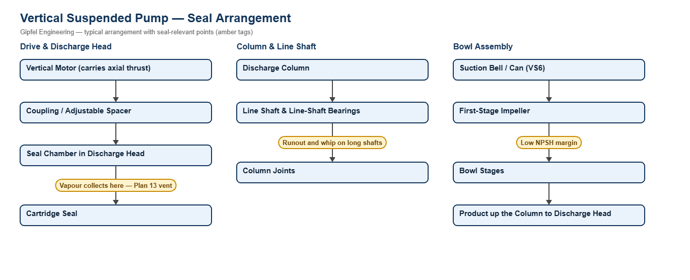
Vertical suspended pumps hang the bowl assembly below the motor on a column and line shaft. API 610 groups them as VS1 (wet-pit turbine), VS4 (sump pump with line-shaft bearings) and VS6 (double-casing can pump). They lift river and cooling water, drain sumps and pits, and handle light hydrocarbons with little NPSH margin.
On most vertical pumps the seal sits at the top, in the discharge head. Two consequences follow. First, any vapour or air in the pumped liquid rises to the seal chamber, so the chamber must be vented, typically with API Plan 13. Second, the seal can see a pressure close to discharge unless a throttle bushing and bleed-off line reduce it, so the seal-chamber pressure must be confirmed from the pump maker before the seal is selected.
Key Sealing Challenges
- Trapped vapour: without venting, the faces run dry at the top of the chamber and fail early. Plan 13 returns seal-chamber liquid to suction and carries vapour with it.
- Long shafts: line-shaft bearing wear allows runout and shaft whip at the seal. Check line-shaft bearings whenever a seal fails.
- Axial setting: the impeller lift is set at the motor or coupling. Setting the seal before setting the impeller lift moves the seal faces off their design length.
- Submersible pumps: the seals run inside the pump, in an oil chamber. Water in the oil is the first sign of lower-seal wear.
Which mechanical seal suits a vertical turbine or can pump?
Use a balanced cartridge seal sized for the confirmed seal-chamber pressure, with API Plan 13 to vent vapour from the top of the chamber. Use SiC vs SiC faces and Plan 32 on sandy water, and a double seal on Plan 52 or 53 for light hydrocarbons in can pumps.
Fault Diagnosis Example
Symptom: Seal on a vertical cooling-water pump fails soon after every restart; faces show dry-running marks.
  ├── Incorrect Response: "Fit a seal with a higher temperature rating."
  ├── Diagnostic Evidence Required:
  │     ├── Is the seal chamber vented? Check for a Plan 13 line or vent and whether it is blocked.
  │     ├── Was the seal set before or after the impeller lift was adjusted?
  │     └── Measure shaft runout at the seal; check line-shaft bearing wear.
  └── Engineered Solution:
        ├── Add or clear a Plan 13 vent line and vent the chamber before start-up.
        ├── Set the impeller lift first, then lock the cartridge seal.
        └── Replace worn line-shaft bearings.
Frequently Asked Questions
Why do vertical pumps use Plan 13 instead of Plan 11?
Plan 11 pushes liquid into the chamber but does not remove the vapour that collects at its top. Plan 13 takes liquid from the seal chamber back to suction, so vapour leaves with it and the faces stay wetted.
Does the seal on a vertical turbine pump see discharge pressure?
It can. The seal sits in the discharge head, so its pressure depends on the throttle bushing and any bleed-off to suction. Confirm the seal-chamber pressure from the pump maker or measure it before choosing the seal.
Can Gipfel supply seals for submersible sewage pumps?
Yes, built to the pump maker’s seal design. Send the pump make, model and serial number, or the old seal.
Related: Municipal Water & Sewage · Pipelines, Terminals & LPG · Between-Bearings Pumps · All process pump solutions.
Request a Seal Selection
Send your pump make and model, fluid, temperature, pressure, shaft size and speed to info@gipfelengg.com or use our enquiry form. Gipfel Engineering (ISO 9001:2015, NSIC-registered MSME, Mumbai) designs and manufactures mechanical seals, seal support systems and process pumps.
Vertical & Submersible Pump Duty & Mechanical Seal Selection Matrix
Typical values for selection guidance only. Final selection is made against the pump data sheet and seal-chamber dimensions.
| Pump type / duty | Typical makes & models | Typical conditions | Seal arrangement | Faces / elastomer | API piping plan |
|---|---|---|---|---|---|
| Vertical turbine / wet-pit pump (VS1) | Vertical turbine pumps from KBL, Sam Turbo and others (model to confirm) | Raw, cooling and process water; seal in the discharge head; pressure set by the throttle bushing and bleed-off | Balanced multi-spring cartridge seal | Carbon vs SiC on clean water; SiC vs SiC on sandy water; EPDM | Plan 13 to vent the chamber; Plan 32 (≈ 1 bar above chamber) on sandy water |
| Double-casing can pump (VS6) | Can-type pumps for LPG, condensate and low-NPSH duty (model to confirm) | Light hydrocarbons near their vapour pressure; seal-chamber pressure to the pump datasheet | Tandem double cartridge seal or Double cartridge seal, back-to-back (pressurised) | SiC vs carbon; FKM or FFKM | Plan 13 inboard venting with Plan 52 (unpressurised) or Plan 53A / 53B (pressurised) |
| Vertical sump pump (VS4) | Refinery and chemical drain-sump pumps (model to confirm) | Seal is above the liquid and sees vapour, not liquid pressure | Balanced multi-spring cartridge seal designed for vapour service | SiC vs carbon; FKM or FFKM | Containment seal arrangements (Plan 72 / 76) where vapour emissions must be controlled — on request |
| Submersible wastewater pump | ITT Flygt N-series and similar submersibles | Seals run in the pump’s oil chamber; lower seal faces the sewage | Double cartridge seal for Flygt-type submersible pumps (built to the pump maker’s design) | SiC vs SiC or tungsten carbide vs tungsten carbide (lower seal); carbon or SiC vs SiC (upper seal); FKM or NBR | Oil chamber between seals — check oil for water at every service |
Reviewed by Gipfel Engineering’s technical team.
Technical Information Disclaimer
The information on this page, including process descriptions, flow diagrams, operating ranges, seal arrangements, materials and piping plans, is general technical guidance for information only. Values shown are typical industry ranges, not guaranteed ratings or specifications of any Gipfel Engineering product. Each application differs. Seal selection, material compatibility, installation and operation must be verified by qualified personnel against the specific equipment data sheet, process conditions, applicable codes and the pump manufacturer’s instructions. A binding recommendation is given only in a written quotation or technical offer from Gipfel Engineering.
References to standards (such as API 682, ISO 21049, ISO 3069, FDA 21 CFR 177.2600 and NACE MR0175 / ISO 15156) describe common industry practice. They do not mean that any product is certified, qualified or approved to that standard unless this is confirmed in writing for a specific order. Third-party company and product names, including “equivalent to” references, are used for identification only and remain the trademarks of their owners. No affiliation, endorsement or OEM approval is implied.
Compliance with safety, hazardous-area, environmental and statutory requirements at the user’s site remains the responsibility of the plant owner or operator. To the extent permitted by law, Gipfel Engineering accepts no liability for loss or damage arising from reliance on this general information without a confirmed written recommendation. Content may change without notice.