
Heavy Slurry & Solids Handling Pumps
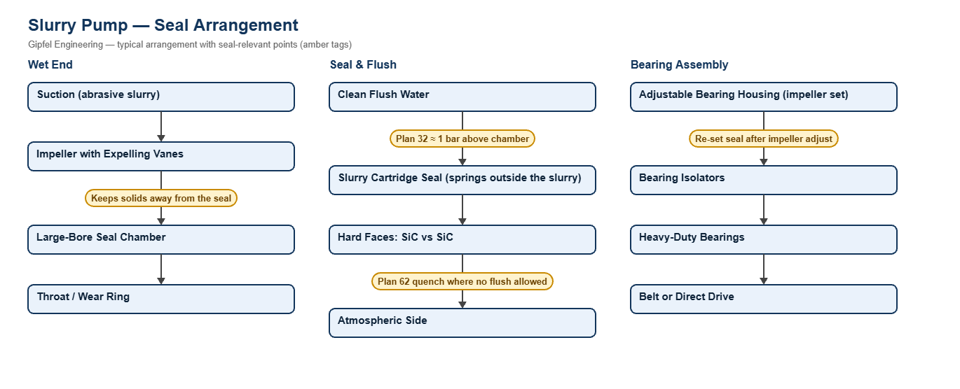
Process Overview
Heavy Slurry & Solids Handling Pumps — Sealing Overview
Slurry pumps move abrasive solids in water: ore and tailings in mineral processing, ash in power plants, limestone and gypsum in flue-gas desulphurisation, and crystallising liquors in sugar and zero-liquid-discharge plants. They are built with thick wear parts, large shafts and an adjustable impeller, and they traditionally run on gland packing with a large flow of gland water, or on an expeller (dynamic seal).
A slurry mechanical seal replaces the packing and removes the gland-water flow that dilutes the product. To survive, it needs hard faces (SiC vs SiC), springs kept out of the slurry, large clearances so solids cannot pack around the faces, and either a clean flush or a quench. Plan 11 is never used on abrasive slurry, because it would blast solids into the seal chamber.
Key Sealing Challenges
- Abrasion: solids erode faces, sleeves and seal chambers. Hard faces and a large-bore chamber reduce wear.
- Packing and caking: solids settle around springs and drive parts, so springs must sit outside the slurry.
- Impeller adjustment: resetting the impeller clearance moves the shaft axially; the seal must be reset after each adjustment.
- Water balance: plants want to cut gland water. A mechanical seal on Plan 32 uses far less flush water than packing, and a quench-only arrangement uses none in the process.
Which mechanical seal suits a slurry pump?
Use a slurry cartridge seal with SiC vs SiC faces and springs outside the slurry (Gipfel HS860), fitted in a large-bore seal chamber. Run it with a Plan 32 clean flush about 1 bar above seal-chamber pressure, or with a Plan 62 quench where dilution is not allowed. Never use Plan 11 on slurry.
Fault Diagnosis Example
Symptom: Slurry pump seal leaks a few weeks after the impeller was adjusted for wear.
  ├── Incorrect Response: "The slurry is too abrasive for a mechanical seal."
  ├── Diagnostic Evidence Required:
  │     ├── Was the seal reset after the impeller was moved?
  │     ├── Is the Plan 32 flush pressure about 1 bar above seal-chamber pressure, and is it on whenever the pump runs?
  │     └── Inspect for solids packed around the faces and springs.
  └── Engineered Solution:
        ├── Reset the cartridge seal (setting clips) after each impeller adjustment.
        ├── Interlock the flush with the pump start and fit a flow indicator.
        └── Use a slurry cartridge seal with springs outside the slurry.
Frequently Asked Questions
Can a slurry pump run a mechanical seal without flush water?
Yes, on many duties. A slurry seal can run without a process-side flush if the impeller expelling vanes keep solids away from the seal and a Plan 62 quench keeps the atmospheric side clean. The choice depends on solids content, particle size and pump design.
How much flush water does a Plan 32 slurry seal need?
Far less than gland packing. The flush only has to keep the seal chamber clean and slightly above process pressure, at about 1 bar above seal-chamber pressure. The flow rate depends on the throat bushing clearance and is set for each pump.
Can an expeller-sealed slurry pump be converted to a mechanical seal?
Usually yes. The expeller is removed or kept as a deflector, and a slurry cartridge seal is fitted to the existing chamber or a replacement seal housing. Send the pump make, model and shaft size.
Related: Alumina & Non-Ferrous · Coal-Fired Thermal Power · Industrial ETP & ZLD · Overhung Pumps · All process pump solutions.
Request a Seal Selection
Send your pump make and model, slurry type and solids content, temperature, pressure, shaft size and speed to info@gipfelengg.com or use our enquiry form. Gipfel Engineering (ISO 9001:2015, NSIC-registered MSME, Mumbai) designs and manufactures mechanical seals, seal support systems and process pumps.
Slurry Pump Duty & Mechanical Seal Selection Matrix
Typical values for selection guidance only. Final selection is made against the pump data sheet, slurry analysis and seal-chamber dimensions.
| Pump type / duty | Typical makes & models | Typical conditions | Seal arrangement | Faces / elastomer | API piping plan |
|---|---|---|---|---|---|
| Hard-metal or rubber-lined slurry pump — mineral processing and tailings | Horizontal centrifugal slurry pumps (model to confirm) | Abrasive ore and tailings slurries; low seal-chamber pressure; adjustable impeller | Slurry cartridge seal, external springs (catalogue ref. HS860) | SiC vs SiC; EPDM | Plan 32 clean water (Plan 32) ≈ 1 bar above chamber, or no flush with Plan 62 water quench where dilution is not allowed |
| Ash slurry pump (power plants) | Bottom-ash and fly-ash slurry pumps (model to confirm) | Abrasive ash slurry; often series pumping, so later stages see higher suction pressure | Slurry cartridge seal, external springs (catalogue ref. HS860) | SiC vs SiC; EPDM | Plan 32 or Plan 62 quench; size each stage for its own seal-chamber pressure |
| FGD limestone and gypsum slurry pump | Absorber recirculation and gypsum bleed pumps (model to confirm) | Abrasive, chloride-bearing slurry | Slurry cartridge seal, external springs (catalogue ref. HS860) | SiC vs SiC; EPDM or FKM; duplex or super-duplex metal parts | Plan 32 or Plan 62 quench |
| Crystallising slurry — salt, ZLD crystalliser and sugar magma | Crystalliser and circulation pumps (model to confirm) | Solids form on the atmospheric side as liquid evaporates | Slurry cartridge seal, external springs (catalogue ref. HS860) | SiC vs SiC; EPDM | Plan 62 quench to dissolve crystals at the faces; Plan 32 where the process allows |
| Large slurry pumps where downtime is costly | Large slurry pumps (model to confirm) | Seal change without removing the drive | Split mechanical seal (on suitable duties) | Carbon or SiC vs SiC; EPDM | Plan 32 |
Reviewed by Gipfel Engineering’s technical team.
Technical Information Disclaimer
The information on this page, including process descriptions, flow diagrams, operating ranges, seal arrangements, materials and piping plans, is general technical guidance for information only. Values shown are typical industry ranges, not guaranteed ratings or specifications of any Gipfel Engineering product. Each application differs. Seal selection, material compatibility, installation and operation must be verified by qualified personnel against the specific equipment data sheet, process conditions, applicable codes and the pump manufacturer’s instructions. A binding recommendation is given only in a written quotation or technical offer from Gipfel Engineering.
References to standards (such as API 682, ISO 21049, ISO 3069, FDA 21 CFR 177.2600 and NACE MR0175 / ISO 15156) describe common industry practice. They do not mean that any product is certified, qualified or approved to that standard unless this is confirmed in writing for a specific order. Third-party company and product names, including “equivalent to” references, are used for identification only and remain the trademarks of their owners. No affiliation, endorsement or OEM approval is implied.
Compliance with safety, hazardous-area, environmental and statutory requirements at the user’s site remains the responsibility of the plant owner or operator. To the extent permitted by law, Gipfel Engineering accepts no liability for loss or damage arising from reliance on this general information without a confirmed written recommendation. Content may change without notice.