Chlor-Alkali Plant
Process Overview
Chlor-Alkali Plant — Process Overview
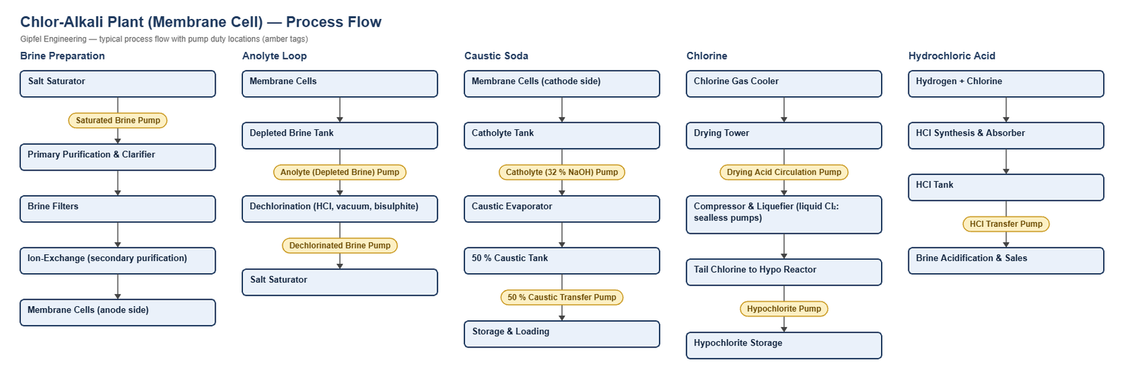
A membrane-cell chlor-alkali plant electrolyses purified saturated brine to produce chlorine, caustic soda and hydrogen. Brine is saturated, purified by precipitation, filtration and ion exchange, and fed to the anode side of the cells. Depleted brine (anolyte) leaves with dissolved chlorine, is dechlorinated and returned to the saturator. Caustic soda leaves the cathode side at about 32 % and is evaporated to 50 %. Chlorine gas is cooled, dried with sulphuric acid, compressed and liquefied; hydrogen and chlorine are combined to make hydrochloric acid, and tail chlorine is absorbed in caustic as sodium hypochlorite.
For sulphuric acid production see Sulphuric Acid; for other chemical duties see General Chemical Plants.
Key Sealing Challenges
- Chlorides and wet chlorine: stainless steel pits and cracks; titanium metal parts are used in wet-chlorine brine. Titanium must not be used in dry chlorine or hot hydrochloric acid.
- Crystallisation: brine and caustic leakage crystallise on the atmospheric side, so an API Plan 62 water quench is standard.
- Caustic soda: attacks the free silicon in reaction-bonded SiC, so sintered SiC faces are specified.
- Purity: membrane cells are sensitive to brine impurities, so seal leakage and quench water must be kept out of the process brine.
What mechanical seal is used for chlorinated brine pumps in chlor-alkali plants?
Anolyte and depleted brine pumps typically use a balanced cartridge seal with titanium metal parts, sintered silicon carbide vs. sintered silicon carbide faces and FFKM elastomers, with an API Plan 11 flush and an API Plan 62 water quench to stop salt crystallising on the atmospheric side. Titanium resists wet chlorine and hot chloride brine; it is not suitable for dry chlorine or hot hydrochloric acid.
Root-Cause Failure Analysis — Field Example
Symptom: Catholyte (32 % NaOH) pump seal leaks after a few months; faces show a grainy, etched surface.
  ├── Incorrect Response: "Increase spring load to close the faces."
  ├── Diagnostic Evidence Required:
  │     ├── Identify face grade: reaction-bonded SiC contains free silicon, which hot caustic leaches out.
  │     ├── Inspect the atmospheric side for caustic crystal build-up hanging up the seal.
  │     └── Confirm the Plan 62 quench is flowing during operation and standby.
  └── Engineered Solution:
        ├── Sintered SiC vs sintered SiC faces with EPDM elastomers.
        ├── Nickel-alloy metal parts for hot caustic.
        └── Continuous Plan 62 low-pressure water quench.
Frequently Asked Questions
Why is sintered silicon carbide specified for caustic soda?
Reaction-bonded silicon carbide contains free silicon metal, which hot caustic soda dissolves, leaving a weakened, porous face. Sintered (self-sintered) silicon carbide has no free silicon and resists caustic.
Are mechanical seals used on liquid chlorine pumps?
Liquid chlorine is normally handled by sealless canned-motor or magnetic-drive pumps, in line with plant safety practice, so no dynamic shaft seal is exposed to the liquid.
Related: Sulphuric Acid · Fertiliser · General Chemical Plants · Wastewater, ETP & ZLD.
Request a Seal Selection
Send your pump make and model, fluid, concentration, temperature, pressure, shaft size and speed to info@gipfelengg.com or use our enquiry form. Gipfel Engineering (ISO 9001:2015, NSIC-registered MSME, Mumbai) designs and manufactures mechanical seals, seal support systems and process pumps.
Equipment solutions: Overhung Pumps · Vertical & Sump Pumps · Compressors & Bearing Chambers.
Pump Duty & Mechanical Seal Selection Matrix
Typical values for selection guidance only. Final selection is made against the customer duty sheet.
| Pump duty | Fluid | Typical temp. | Typical pressure (bar) | Seal arrangement | Faces / elastomer | API piping plan |
|---|---|---|---|---|---|---|
| Saturated Brine Pump | Saturated NaCl brine (raw or treated) | 50–70 °C | 3–5 bar | Balanced multi-spring cartridge with titanium or Hastelloy C-276 metal parts | Sintered SiC vs sintered SiC / EPDM | API Plan 11 (filtered brine) or Plan 32 (raw brine with solids) + Plan 62 water quench against salt crystallisation |
| Anolyte (Depleted Brine) Pump | Depleted brine with dissolved wet chlorine, acidic | 80–90 °C | 2–4 bar | Balanced multi-spring cartridge with titanium metal parts | Sintered SiC vs sintered SiC / FFKM | API Plan 11 + Plan 62 water quench |
| Dechlorinated Brine Pump | Dechlorinated brine | 70–85 °C | 3–5 bar | Balanced multi-spring cartridge with titanium or Hastelloy C-276 metal parts | Sintered SiC vs sintered SiC / EPDM or FKM | API Plan 11 + Plan 62 water quench |
| Catholyte (32 % NaOH) Circulation Pump | 32 % caustic soda | 85–90 °C | 2–4 bar | Balanced multi-spring cartridge with nickel-alloy metal parts | Sintered SiC vs sintered SiC (not reaction-bonded) / EPDM | API Plan 11 + Plan 62 water quench against caustic crystallisation |
| 50 % Caustic Transfer / Loading Pump | 50 % caustic soda (cooled) | 40–60 °C | 3–6 bar | Balanced multi-spring cartridge with 316L or nickel-alloy metal parts | Sintered SiC vs sintered SiC / EPDM | API Plan 11 + Plan 62 water quench (50 % NaOH crystallises on cooling) |
| Chlorine Drying Acid Circulation Pump | 78–98 % H₂SO₄ (with dissolved chlorine) | 20–40 °C | 2–4 bar | Balanced multi-spring cartridge with Alloy 20 or Hastelloy C-276 metal parts | Sintered SiC vs sintered SiC / FFKM or PTFE | API Plan 11. No water quench on concentrated acid |
| Sodium Hypochlorite Pump | 10–15 % NaOCl | Ambient–35 °C | 2–4 bar | Balanced multi-spring cartridge with titanium or Hastelloy C-276 metal parts | Sintered SiC vs sintered SiC / FKM or EPDM | API Plan 11 |
| Hydrochloric Acid Transfer Pump | 30–33 % HCl | Ambient–40 °C | 2–4 bar | Usually a lined or non-metallic pump. Seal wetted parts in PTFE, ceramic or tantalum, or Hastelloy B-type only where no free chlorine or other oxidisers are present (not titanium or stainless steel). Selection on request | Sintered SiC vs sintered SiC / FFKM | API Plan 11 |
| Liquid Chlorine Transfer | Liquid chlorine | Ambient (under pressure) | Vapour pressure + head | Normally sealless (canned motor or magnetic drive) pumps, per plant safety practice | — | — |
Reviewed by Gipfel Engineering’s technical team.
Technical Information Disclaimer
The information on this page, including process descriptions, flow diagrams, operating ranges, seal arrangements, materials and piping plans, is general technical guidance for information only. Values shown are typical industry ranges, not guaranteed ratings or specifications of any Gipfel Engineering product. Each application differs. Seal selection, material compatibility, installation and operation must be verified by qualified personnel against the specific equipment data sheet, process conditions, applicable codes and the pump manufacturer’s instructions. A binding recommendation is given only in a written quotation or technical offer from Gipfel Engineering.
References to standards (such as API 682, ISO 21049, ISO 3069, FDA 21 CFR 177.2600 and NACE MR0175 / ISO 15156) describe common industry practice. They do not mean that any product is certified, qualified or approved to that standard unless this is confirmed in writing for a specific order. Third-party company and product names, including “equivalent to” references, are used for identification only and remain the trademarks of their owners. No affiliation, endorsement or OEM approval is implied.
Compliance with safety, hazardous-area, environmental and statutory requirements at the user’s site remains the responsibility of the plant owner or operator. To the extent permitted by law, Gipfel Engineering accepts no liability for loss or damage arising from reliance on this general information without a confirmed written recommendation. Content may change without notice.