
Industrial Blenders
Process Overview
Industrial Blenders — Sealing Overview
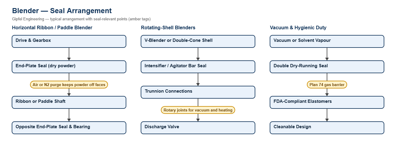
Blenders mix dry powders, granules and pastes in food, pharmaceutical, chemical, fertiliser and plastics plants. Horizontal ribbon and paddle blenders turn a shaft inside a fixed trough; V-blenders and double-cone blenders rotate the whole shell, sometimes with an intensifier bar passing through it; vacuum blenders mix and dry in a closed vessel.
The seal sits where the shaft passes through the end plates or shell, in contact with dry powder rather than liquid. Fine powder works into the faces and secondary seals, so the seal must run dry and be kept clean with a gas purge or a gas barrier. Traditional gland packing on blenders sheds fibres into the product and lets powder escape; dry-running mechanical seals avoid both.
Key Sealing Challenges
- Powder ingress: a clean air or nitrogen purge at the seal keeps product away from the faces.
- Access: large blenders are hard to dismantle, so split seals that fit around the shaft save downtime.
- Vacuum and vapour: closed and vacuum blenders need double seals with a gas barrier to hold vacuum and contain solvent vapour.
- Hygiene: food and pharmaceutical blenders need cleanable seals, FDA-compliant elastomers and resin-impregnated carbon.
Which seal suits a ribbon blender?
Use a dry-running mechanical seal at each end plate with a clean air or nitrogen purge to keep powder off the faces, or a split mechanical seal where the blender is hard to dismantle. Use a double dry-running seal on a Plan 74 nitrogen barrier on vacuum or toxic duty.
Fault Diagnosis Example
Symptom: Powder leaks at the end plates of a ribbon blender and the seal faces wear quickly.
  ├── Incorrect Response: "Tighten the packing."
  ├── Diagnostic Evidence Required:
  │     ├── Is there a purge at the seal, and is it on whenever the blender runs?
  │     ├── Check end-plate alignment and shaft runout at both ends.
  │     └── Are the existing seals designed to run dry?
  └── Engineered Solution:
        ├── Fit dry-running seals with a filtered air or nitrogen purge.
        ├── Correct shaft alignment between the end bearings.
        └── Use split seals where removing the shaft is impractical.
Frequently Asked Questions
Why replace blender packing with a mechanical seal?
Packing wears the shaft, lets powder escape and can shed fibres into the product. A dry-running mechanical seal with a purge keeps the product in and the shaft undamaged.
How are rotating-shell blenders sealed?
The intensifier or agitator bar passing through the shell uses a dry-running shaft seal, and the vacuum and heating lines through the trunnions use rotary joints.
Related: Industrial Mixers · Dryers & ANFD · API & Bulk Drug · All blender solutions.
Request a Seal Selection
Send the blender drawing, shaft size and speed, product and any vacuum or pressure to info@gipfelengg.com or use our enquiry form. Gipfel Engineering (ISO 9001:2015, NSIC-registered MSME, Mumbai) designs and manufactures mechanical seals, seal support systems and process pumps.
Blender Duty & Mechanical Seal Selection Matrix
Typical values for selection guidance only. Final selection is made against the blender drawing, shaft size, product and pressure or vacuum.
| Blender type / duty | Typical equipment | Typical conditions | Seal arrangement | Faces / elastomer | Purge / barrier |
|---|---|---|---|---|---|
| Ribbon and paddle blender — dry powders at atmospheric pressure | Horizontal ribbon and paddle blenders | Slow horizontal shaft; fine powder at both end plates | Single dry mechanical seal, or Split mechanical seal where the blender cannot easily be dismantled | Dry-running faces (carbon vs SiC); FKM or EPDM | Clean air or nitrogen purge at the seal to keep powder off the faces |
| Vacuum blender and blenders handling solvents or toxic powders | Vacuum and closed blenders | Vacuum; solvent vapour or toxic dust must be contained | Double dry-running seal (gas barrier) | Gas-lubricated faces to the seal datasheet; FKM or FFKM | Plan 74 nitrogen barrier above blender pressure |
| V-blender and double-cone blender | Rotating-shell blenders | The shell rotates; an intensifier or agitator bar may pass through it; vacuum and heating lines pass through the trunnions | Single dry-running seal with bearing support for the intensifier bar; Rotary joints for trunnion connections | Dry-running carbon vs SiC; FDA-compliant elastomers on food and pharma duty | Purge at the intensifier seal; rotary joints selected for each medium |
| Food and pharmaceutical (cGMP) blenders | Hygienic blenders | Cleanable, FDA-compliant materials required | Single dry mechanical seal or Double dry-running seal (gas barrier) | Resin-impregnated carbon vs SiC; elastomers to FDA 21 CFR 177.2600 | Filtered air or nitrogen purge |
Reviewed by Gipfel Engineering’s technical team.
Technical Information Disclaimer
The information on this page, including process descriptions, flow diagrams, operating ranges, seal arrangements, materials and piping plans, is general technical guidance for information only. Values shown are typical industry ranges, not guaranteed ratings or specifications of any Gipfel Engineering product. Each application differs. Seal selection, material compatibility, installation and operation must be verified by qualified personnel against the specific equipment data sheet, process conditions, applicable codes and the pump manufacturer’s instructions. A binding recommendation is given only in a written quotation or technical offer from Gipfel Engineering.
References to standards (such as API 682, ISO 21049, ISO 3069, FDA 21 CFR 177.2600 and NACE MR0175 / ISO 15156) describe common industry practice. They do not mean that any product is certified, qualified or approved to that standard unless this is confirmed in writing for a specific order. Third-party company and product names, including “equivalent to” references, are used for identification only and remain the trademarks of their owners. No affiliation, endorsement or OEM approval is implied.
Compliance with safety, hazardous-area, environmental and statutory requirements at the user’s site remains the responsibility of the plant owner or operator. To the extent permitted by law, Gipfel Engineering accepts no liability for loss or damage arising from reliance on this general information without a confirmed written recommendation. Content may change without notice.