API & Bulk Drug Manufacturing
Process Overview
API & Bulk Drug Manufacturing — Process Overview
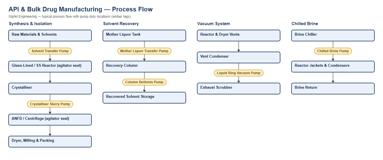
Active pharmaceutical ingredient (API) and bulk drug plants make drug substances by multi-step chemical synthesis in batch reactors. Each step charges solvents and reagents, reacts them under controlled temperature and pressure, then crystallises, filters and dries the product in agitated nutsche filter dryers (ANFD) or centrifuges. Solvents are recovered by distillation, and vacuum and chilled brine systems serve the reactors.
For fermentation, cell culture, WFI and sterile processing see Biotech & Sterile Manufacturing.
Key Sealing Challenges
- Changing chemistry: one reactor may see acids, bases and many solvents in a campaign, so FFKM elastomers and high-alloy wetted parts are standard.
- Containment: toxic and flammable solvents are kept in the vessel with double agitator seals on a pressurised barrier.
- Vacuum and pressure cycling: reactors and dryers swing from full vacuum to positive pressure; the seal must hold in both directions.
- Product purity: barrier fluid and wear particles must not contaminate the batch.
What mechanical seal is used on glass-lined reactor agitators?
Glass-lined reactor agitators typically use a double cartridge agitator seal with an integral bearing, with FFKM elastomers and Hastelloy C or PTFE-protected wetted parts, on a pressurised barrier at least 1.4 bar above vessel pressure. The barrier keeps solvent vapour in the vessel during pressure and full-vacuum steps, and the bearing controls shaft run-out at the seal.
Root-Cause Failure Analysis — Field Example
Symptom: Reactor agitator seal barrier level drops and the barrier fluid is found in the batch.
  ├── Incorrect Response: "Fit stronger springs."
  ├── Diagnostic Evidence Required:
  │     ├── Is barrier pressure held above vessel pressure during every step, including pressure transfers?
  │     ├── Measure shaft run-out and deflection at the seal: is the agitator bearing worn?
  │     └── Check the inboard elastomer against the solvents used in the campaign.
  └── Engineered Solution:
        ├── Set barrier pressure at least 1.4 bar above the highest vessel pressure.
        ├── Double agitator seal with integral bearing to control run-out.
        └── FFKM elastomers and a barrier fluid acceptable to the product (e.g. a pharmaceutical-grade fluid).
Frequently Asked Questions
Why use FFKM in API plants?
A multi-purpose plant may process methanol, acetone, toluene, MDC, acids and bases in one campaign. FFKM resists almost all of them, while EPDM fails in aromatics and FKM fails in ketones and amines.
Which seal suits an ANFD agitator?
A double agitator seal with an integral bearing, on a pressurised liquid or nitrogen barrier, holds both vacuum drying and positive-pressure filtration while keeping the product free of contamination.
Related: Biotech & Sterile Manufacturing · General Chemical Plants · Food & Dairy · Industrial ETP & ZLD.
Request a Seal Selection
Send your pump make and model, fluid, temperature, pressure, shaft size and speed to info@gipfelengg.com or use our enquiry form. Gipfel Engineering (ISO 9001:2015, NSIC-registered MSME, Mumbai) designs and manufactures mechanical seals, seal support systems and process pumps.
Equipment solutions: Reactors & GLR · Dryers & ANFD · Agitators.
Pump Duty & Mechanical Seal Selection Matrix
Typical values for selection guidance only. Final selection is made against the customer duty sheet.
| Equipment / duty | Fluid | Typical temp. | Typical pressure (bar) | Seal arrangement | Faces / elastomer | API piping plan |
|---|---|---|---|---|---|---|
| Glass-Lined Reactor Agitator (top-entry) | Solvents, acids and intermediates | −20 to 150 °C | Full vacuum to 6 bar | Double agitator seal with bearing assembly with Hastelloy C or PTFE-protected wetted parts | SiC vs carbon or SiC vs SiC / FFKM | Pressurised barrier (thermosyphon or circulation unit), ≥ 1.4 bar above vessel pressure |
| Stainless Steel Reactor Agitator | Solvents and reaction mass | −20 to 150 °C | Full vacuum to 6 bar | Double agitator seal with bearing assembly | SiC vs carbon / FFKM | Pressurised barrier, ≥ 1.4 bar above vessel pressure |
| Agitated Nutsche Filter Dryer (ANFD) Agitator | Wet cake with solvent; vacuum drying | Ambient–120 °C | Full vacuum to 3 bar | Double agitator seal with bearing assembly (liquid or nitrogen barrier) | SiC vs carbon / FFKM | Pressurised liquid or nitrogen barrier above vessel pressure |
| Solvent Transfer Pump | Methanol, acetone, toluene, MDC, IPA | Ambient–60 °C | 2–6 bar | Balanced multi-spring cartridge; Tandem double cartridge (Arrangement 2) for toxic or highly volatile solvents | SiC vs carbon / FFKM (covers all solvents; EPDM only for methanol / acetone, FKM only for aromatics) | API Plan 11; Plan 11 + Plan 52 for tandem seals |
| Solvent Recovery Column Bottoms Pump | Solvent with residues | 60–120 °C | Low suction pressure — confirm per pump | Balanced multi-spring cartridge | SiC vs SiC / FFKM | API Plan 11 |
| Crystalliser Slurry Pump | API crystals in mother liquor | 0–60 °C | 2–5 bar | Double cartridge, back-to-back (pressurised) | SiC vs SiC / FFKM | API Plan 53A (barrier ≥ 1.4 bar above seal chamber) |
| Mother Liquor / Effluent Transfer Pump | Mixed solvents and salts | Ambient–50 °C | 2–5 bar | Balanced multi-spring cartridge | SiC vs SiC / FFKM | API Plan 11 |
| Liquid Ring Vacuum Pump | Service liquid with condensed solvent vapour | Ambient–40 °C | Suction under vacuum | Single-spring cartridge | SiC vs carbon / FFKM or FKM | Seal flushed from service liquid (Plan 11 / Plan 32 per pump design) |
| Chilled Brine / Glycol Circulation Pump | Brine or glycol solution | −20 to 5 °C | 3–6 bar | Balanced multi-spring cartridge | SiC vs carbon / EPDM | API Plan 11; Plan 62 quench where ice forms on the atmospheric side |
Reviewed by Gipfel Engineering’s technical team.
Technical Information Disclaimer
The information on this page, including process descriptions, flow diagrams, operating ranges, seal arrangements, materials and piping plans, is general technical guidance for information only. Values shown are typical industry ranges, not guaranteed ratings or specifications of any Gipfel Engineering product. Each application differs. Seal selection, material compatibility, installation and operation must be verified by qualified personnel against the specific equipment data sheet, process conditions, applicable codes and the pump manufacturer’s instructions. A binding recommendation is given only in a written quotation or technical offer from Gipfel Engineering.
References to standards (such as API 682, ISO 21049, ISO 3069, FDA 21 CFR 177.2600 and NACE MR0175 / ISO 15156) describe common industry practice. They do not mean that any product is certified, qualified or approved to that standard unless this is confirmed in writing for a specific order. Third-party company and product names, including “equivalent to” references, are used for identification only and remain the trademarks of their owners. No affiliation, endorsement or OEM approval is implied.
Compliance with safety, hazardous-area, environmental and statutory requirements at the user’s site remains the responsibility of the plant owner or operator. To the extent permitted by law, Gipfel Engineering accepts no liability for loss or damage arising from reliance on this general information without a confirmed written recommendation. Content may change without notice.