
Co-Generation & Biomass Power Plant
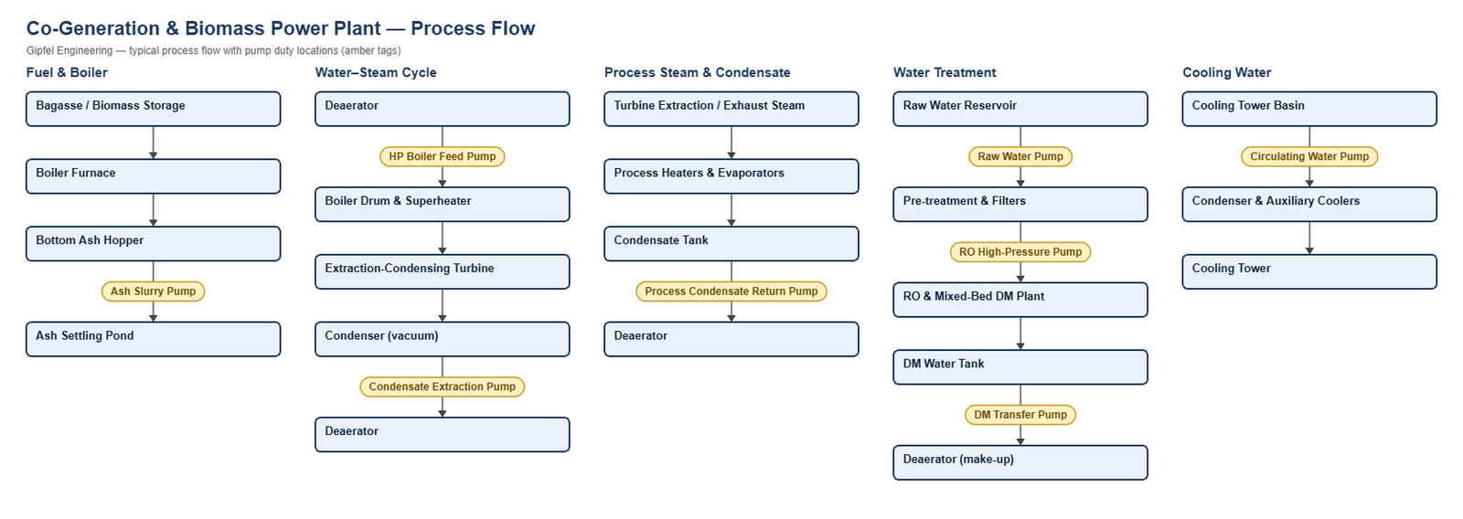
Process Overview
Co-Generation & Biomass Power Plant — Process Overview
A co-generation plant produces electricity and process steam from one boiler. It is common in sugar mills (bagasse), distilleries, paper mills, rice mills and process industries, firing bagasse, rice husk, wood chips or other biomass, sometimes co-fired with coal. Steam from an extraction-condensing or back-pressure turbine supplies the factory, and process condensate returns to the deaerator.
Compared with a utility coal station, units are smaller, run at variable load and often stop for the off-season, and biomass ash is high in silica. For pulverised-coal utility units see Coal-Fired Thermal Power; for gas-turbine plants see Combined Cycle (CCGT).
Key Sealing Challenges
- HP boiler feed pumps: hot feedwater close to saturation. The seal is sized for seal-chamber pressure and cooled with API Plan 23.
- Process condensate return: temperature varies with factory load and the condensate may carry sugar or product traces that crystallise on the atmospheric side.
- Biomass ash: silica-rich slurry wears soft faces and clogs springs; slurry cartridges with external springs and a clean flush are used.
- Seasonal campaigns: seals stand idle for months, so restart checks and preservation matter as much as seal selection.
What mechanical seal is used on a co-generation boiler feed pump?
Co-generation boiler feed pumps typically use a balanced cartridge seal with stationary springs (e.g. Gipfel HP760) on an API Plan 23 cooling circuit, with silicon carbide vs. carbon faces. The seal is selected for seal-chamber pressure (close to suction or balance-line pressure), not boiler or discharge pressure, so the same seal family can serve different boiler ratings once the pump datasheet is checked.
Root-Cause Failure Analysis — Field Example
Symptom: Process condensate return pump seal leaks within days of the season start-up.
  ├── Incorrect Response: "Fit harder seal faces."
  ├── Diagnostic Evidence Required:
  │     ├── Inspect the atmospheric side: crystallised sugar or product deposits around the faces and secondary seal?
  │     ├── Check faces for chipped edges from start-up with faces bonded together after the idle period.
  │     └── Test condensate for carry-over (conductivity / sugar test) and review the restart procedure.
  └── Engineered Solution:
        ├── Add an API Plan 62 low-pressure water quench to dissolve carry-over on the atmospheric side.
        ├── Flush and fill the pump, then turn the shaft by hand before restart.
        └── Use SiC vs carbon faces with EPDM elastomers suited to hot water.
Frequently Asked Questions
Why does biomass ash damage pump seals?
Bagasse and rice-husk ash contain silica that abrades carbon faces and packs around springs. Ash slurry pumps use a slurry cartridge with external springs and silicon carbide or tungsten carbide faces, with an API Plan 32 clean water flush about 1 bar above seal-chamber pressure.
Can one seal serve both 67 bar and 110 bar boilers?
Possibly. The seal sees seal-chamber pressure, not boiler pressure, so selection depends on the pump’s suction and balance-line pressure, temperature, shaft size and speed. Send the pump datasheet for confirmation.
Related: Coal-Fired Thermal Power · Combined Cycle (CCGT) · Cane Sugar Mill · Molasses-Based Distillery.
Request a Seal Selection
Send your pump make and model, fluid, temperature, pressure, shaft size and speed to info@gipfelengg.com or use our enquiry form. Gipfel Engineering (ISO 9001:2015, NSIC-registered MSME, Mumbai) designs and manufactures mechanical seals, seal support systems and process pumps.
Equipment solutions: Boiler Feed & Multistage Pumps · Turbines · Slurry Pumps.
Pump Duty & Mechanical Seal Selection Matrix
Typical values for selection guidance only. Final selection is made against the customer duty sheet.
| Pump duty | Fluid | Typical temp. | Typical pressure (bar) | Seal arrangement | Faces / elastomer | API piping plan |
|---|---|---|---|---|---|---|
| HP Boiler Feed Pump | Deaerated feedwater | 105–160 °C (depends on deaerator and HP heater arrangement) | Discharge 70–140 bar. The seal sees seal-chamber (suction / balance-line) pressure, not discharge — confirm per pump | High-pressure balanced cartridge, stationary springs (catalogue ref. HP760) | Reaction-bonded SiC vs electro-graphite carbon / EPDM (peroxide-cured) or FEPM (Aflas) | API Plan 23 (pumping ring + seal cooler) |
| Deaerator Feed / Condensate Transfer Pump | Condensate and DM make-up | 60–100 °C | 3–8 bar | Balanced multi-spring cartridge | SiC vs carbon / EPDM | API Plan 11; Plan 23 where fluid temperature exceeds the seal datasheet limit |
| Condensate Extraction Pump (CEP) | Turbine condensate | 40–55 °C | Suction under condenser vacuum — confirm seal-chamber pressure per pump | Balanced multi-spring cartridge; Double cartridge, back-to-back (pressurised) where air ingress is critical | SiC vs carbon / EPDM | API Plan 32 (condensate injection) + Plan 62 quench, or dual seal with Plan 53A |
| Process Condensate Return Pump | Factory process condensate (possible sugar or product carry-over) | 80–100 °C | 2–6 bar | Balanced multi-spring cartridge | SiC vs carbon / EPDM | API Plan 11 + Plan 62 water quench to keep carry-over from crystallising on the atmospheric side |
| Cooling Tower Circulating Water Pump | Recirculating cooling water | 30–42 °C | 2–4 bar | Balanced multi-spring cartridge | SiC vs SiC / EPDM | API Plan 11 (clarified water) or Plan 32 (silt-laden water) |
| Raw Water / Pre-treatment Pump | Raw water | Ambient | 2–5 bar | Wave-spring semi-cartridge | SiC vs SiC / EPDM | API Plan 11 (clean) or Plan 32 (silt-laden) |
| RO High-Pressure Feed Pump (DM plant) | Pre-treated water | Ambient | 10–25 bar | Balanced multi-spring cartridge | SiC vs carbon / EPDM | API Plan 11 |
| Boiler Blowdown / Drain Flash Pump | Hot blowdown water | 100–140 °C | 2–6 bar | Balanced multi-spring cartridge | SiC vs carbon / EPDM (peroxide-cured) or FEPM | API Plan 23 |
| Ash Slurry / Wet Ash Handling Pump | Bagasse or biomass ash slurry, high silica | 30–60 °C | 2–6 bar | Slurry cartridge, external springs (catalogue ref. HS860) | SiC vs SiC, or tungsten carbide vs tungsten carbide / FKM or EPDM | API Plan 32 (clean water flush, ≈ 1 bar above seal chamber) |
| Wet Scrubber Recirculation Pump (where fitted) | Scrubber water with fly ash, mildly acidic | 40–60 °C | 2–4 bar | Slurry cartridge, external springs (catalogue ref. HS860) | SiC vs SiC / FKM | API Plan 32 |
Reviewed by Gipfel Engineering’s technical team.
Technical Information Disclaimer
The information on this page, including process descriptions, flow diagrams, operating ranges, seal arrangements, materials and piping plans, is general technical guidance for information only. Values shown are typical industry ranges, not guaranteed ratings or specifications of any Gipfel Engineering product. Each application differs. Seal selection, material compatibility, installation and operation must be verified by qualified personnel against the specific equipment data sheet, process conditions, applicable codes and the pump manufacturer’s instructions. A binding recommendation is given only in a written quotation or technical offer from Gipfel Engineering.
References to standards (such as API 682, ISO 21049, ISO 3069, FDA 21 CFR 177.2600 and NACE MR0175 / ISO 15156) describe common industry practice. They do not mean that any product is certified, qualified or approved to that standard unless this is confirmed in writing for a specific order. Third-party company and product names, including “equivalent to” references, are used for identification only and remain the trademarks of their owners. No affiliation, endorsement or OEM approval is implied.
Compliance with safety, hazardous-area, environmental and statutory requirements at the user’s site remains the responsibility of the plant owner or operator. To the extent permitted by law, Gipfel Engineering accepts no liability for loss or damage arising from reliance on this general information without a confirmed written recommendation. Content may change without notice.