General Chemical Plants
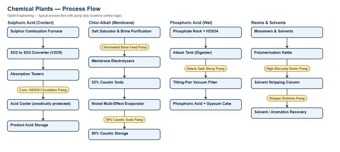
Process Overview
General Chemical Plants — Process Overview
Chemical and petrochemical plants combine the most demanding sealing conditions in industry: hot concentrated mineral acids (sulphuric, nitric, phosphoric), concentrated caustic soda, chlorinated brine, abrasive acid slurries, very viscous resins and toxic volatile organics. Seal selection is driven first by material compatibility, then by crystallisation, abrasion and emission control.
Primary Chemical Sectors Covered:
- Mineral acids: sulphuric acid (contact process), nitric acid and wet-process phosphoric acid.
- Chlor-alkali: membrane-cell brine electrolysis and caustic soda evaporation to 50%.
- Fertilisers: phosphoric acid attack-tank slurries and nitrogen chemicals.
- Petrochemicals & solvents: aromatics (BTX) distillation and solvent recovery.
- Resins & specialty chemicals: epoxy, alkyd and polyol resins, batch reactors.
What mechanical seal is used for 98% sulphuric acid pumps?
Hot concentrated sulphuric acid pumps typically use a single balanced cartridge seal with springs kept outside the acid, sintered silicon carbide vs. silicon carbide faces, FFKM elastomers and alloy wetted parts such as Alloy 20 or Hastelloy C, chosen for the acid strength and temperature. A water quench must never be used on concentrated acid; where a quench is needed, dry nitrogen is used.
Engineering Notes
- Caustic soda: 50% NaOH crystallises on contact with air and when it cools. A continuous low-pressure water quench (Plan 62) with a throttle bushing dissolves weepage before it locks the springs.
- Wet chlorine and brine: titanium resists wet chlorine and chloride pitting, but must not be used in dry chlorine.
- Volatile organics: dual pressurised seals (Plan 53A) keep the faces in clean barrier liquid and minimise fugitive emissions.
- Viscous resins: a heated barrier circuit (Plan 54) stops resin solidifying between the faces.
Root-Cause Failure Analysis — Field Example
Symptom: 50% caustic soda pump will not turn after a 3-day shutdown; seal leaks on restart.
  ├── Diagnostic Evidence Required:
  │     ├── Atmospheric side: is hard white caustic / carbonate crust present?
  │     ├── Springs: are they encrusted and unable to move?
  │     ├── O-rings: is the dynamic O-ring cemented to the sleeve?
  └── Engineered Solution:
        ├── Fit a single balanced cartridge seal with throttle bushing and API Plan 62 quench.
        ├── Run a continuous low-pressure condensate or soft-water quench, including during shutdowns.
        ├── The quench dissolves weepage before it reacts with air and crystallises.
Operational & Environmental Benefits
- Lower fugitive emissions: dual pressurised seals on aromatic and solvent pumps keep process fluid behind a barrier liquid, reducing emissions and operator exposure.
- Safer acid service: correct alloy selection and springs kept out of the acid reduce the risk of sudden seal failure on hot acid loops.
Frequently Asked Questions
Why do mechanical seals seize on 50% caustic soda pumps?
50% caustic soda solidifies at around 12 °C and reacts with carbon dioxide in air to form hard carbonate scale. Weepage crystallises behind the dynamic O-ring and locks the springs. A Plan 62 water quench on the atmospheric side dissolves the weepage continuously and prevents seizure.
What metallurgy is used for wet chlorine and chlorinated brine pumps?
Wet chlorine and chlorinated brine cause pitting and crevice corrosion in 316L and duplex steels. Titanium Grade 2 or Hastelloy C wetted parts with silicon carbide faces and FFKM O-rings give high resistance. Titanium is suitable for wet chlorine only, never dry chlorine.
Dedicated process pages: Sulphuric Acid · Chlor-Alkali · Fertiliser.
Request a Seal Selection
Send your pump make and model, fluid and concentration, temperature, pressure, shaft size and speed to info@gipfelengg.com or use our enquiry form. Related: wastewater & ZLD, pharmaceutical. Gipfel Engineering (ISO 9001:2015, NSIC-registered MSME, Mumbai) designs and manufactures mechanical seals, seal support systems and process pumps.
Equipment solutions: Overhung Pumps · Agitators · Reactors & GLR.
Pump Duty & Mechanical Seal Selection Matrix
Typical values for selection guidance only. Final selection is made against the customer duty sheet and material compatibility check.
| Pump duty | Fluid | Typical temp. | Typical pressure (bar) | Seal arrangement | Faces / elastomer | API piping plan |
|---|---|---|---|---|---|---|
| 98.5% Sulphuric Acid Circulation | Concentrated H2SO4 (98.5%) | 75–115°C | 4.0–7.5 | Single balanced cartridge, springs outside the acid; alloy hardware (e.g. Alloy 20 / Hastelloy C) selected per duty | Sintered SiC vs sintered SiC / FFKM | API Plan 11 or Plan 02. Plan 62 only with dry N2 — never a water quench on concentrated acid |
| 50% Caustic Soda Transfer | 50% NaOH | 50–75°C | 3.5–6.0 | Single balanced cartridge with throttle bushing | Sintered SiC vs sintered SiC (not reaction-bonded) / EPDM or Aflas | API Plan 11 + Plan 62 (continuous low-pressure water or condensate quench) |
| Chlorinated Brine Feed | Saturated NaCl brine + dissolved chlorine | 65–85°C | 4.0–6.5 | Single cartridge, titanium Gr. 2 or Hastelloy C wetted parts (wet-chlorine service only) | Sintered SiC vs sintered SiC / FFKM | API Plan 32 (clean dechlorinated brine) or Plan 11 |
| Phosphoric Acid Attack-Tank Slurry | H3PO4 + H2SO4 + gypsum crystals | 75–85°C | 3.5–5.5 | Heavy slurry cartridge, springs out of the product; high-alloy wetted parts (catalogue ref. HS860) | Sintered SiC vs sintered SiC / FKM or FFKM (no cobalt-bound tungsten carbide) | API Plan 32 (clean water flush) |
| Resin Transfer (positive-displacement pump) | Hot-melt alkyd / polyester resin, very high viscosity | 140–200°C | 6–15 | Dual pressurised cartridge with heated barrier | SiC vs SiC / high-temperature FFKM | API Plan 54 (heated barrier circuit) |
| Benzene / Toluene Stripper Bottoms | Hot aromatic hydrocarbons | 95–130°C | 3.0–5.5 | Dual pressurised cartridge | Carbon vs SiC / FFKM | API Plan 53A (barrier ≥ 1.4 bar / 20 psi above seal-chamber pressure) |
| 65% Nitric Acid Transfer | HNO3 (65%) | 35–60°C | 4.0–6.0 | Single balanced cartridge, titanium or 304L wetted parts | SiC vs SiC / PTFE-encapsulated or FFKM | API Plan 11 |
Reviewed by Gipfel Engineering’s technical team.
Technical Information Disclaimer
The information on this page, including process descriptions, flow diagrams, operating ranges, seal arrangements, materials and piping plans, is general technical guidance for information only. Values shown are typical industry ranges, not guaranteed ratings or specifications of any Gipfel Engineering product. Each application differs. Seal selection, material compatibility, installation and operation must be verified by qualified personnel against the specific equipment data sheet, process conditions, applicable codes and the pump manufacturer’s instructions. A binding recommendation is given only in a written quotation or technical offer from Gipfel Engineering.
References to standards (such as API 682, ISO 21049, ISO 3069, FDA 21 CFR 177.2600 and NACE MR0175 / ISO 15156) describe common industry practice. They do not mean that any product is certified, qualified or approved to that standard unless this is confirmed in writing for a specific order. Third-party company and product names, including “equivalent to” references, are used for identification only and remain the trademarks of their owners. No affiliation, endorsement or OEM approval is implied.
Compliance with safety, hazardous-area, environmental and statutory requirements at the user’s site remains the responsibility of the plant owner or operator. To the extent permitted by law, Gipfel Engineering accepts no liability for loss or damage arising from reliance on this general information without a confirmed written recommendation. Content may change without notice.