
Between-Bearings Split-Case Pumps
Process Overview
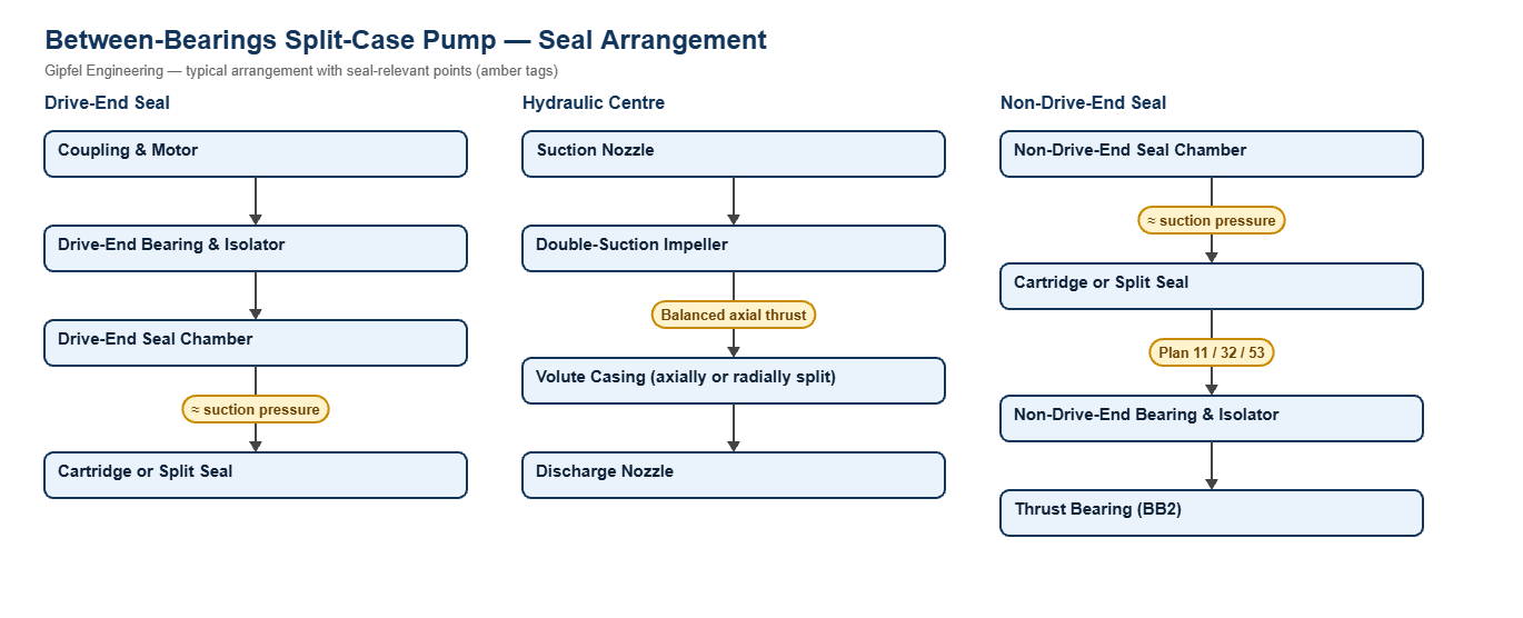
Between-Bearings Split-Case Pumps — Sealing Overview
Between-bearings pumps support the impeller on a shaft carried by bearings at both ends. Single- and two-stage designs include axially split (API 610 BB1) and radially split (BB2) pumps, most often with a double-suction impeller. They move large flows of raw water, cooling water, seawater, fire water and pipeline products.
Each pump has two seals, one at the drive end and one at the non-drive end. With a double-suction impeller both seal chambers sit close to suction pressure, so the seals see far less pressure than the discharge gauge suggests. Because the shaft is supported at both ends, deflection at the faces is low, and seal life is usually limited by the water quality, by bearing condition or by how the seals are fitted.
Key Sealing Challenges
- Two seals per pump: both must be replaced and set correctly; a mis-set non-drive-end seal is a common cause of repeat failures.
- Downtime: replacing a solid seal on a large split-case pump means uncoupling the motor and often lifting the top casing. A split seal can be fitted around the shaft instead.
- Sand and silt: raw water and seawater carry abrasives into the seal chamber; hard faces and a clean external flush protect them.
- Bearing contamination: leakage and wash-down water reach the bearing housings. Non-contacting bearing isolators keep the oil clean.
Which mechanical seal suits a between-bearings split-case pump?
On clean water use a balanced cartridge seal at each end, sized for seal-chamber pressure (close to suction), with Plan 11. Use SiC vs SiC faces and Plan 32 on sandy water, a split seal where removing the motor is costly, and Plan 23 on hot water.
Fault Diagnosis Example
Symptom: Non-drive-end seal on a split-case cooling-water pump fails repeatedly; the drive-end seal lasts.
  ├── Incorrect Response: "Change the seal supplier."
  ├── Diagnostic Evidence Required:
  │     ├── Check the seal setting length against the drawing; was the sleeve located after the impeller was centred?
  │     ├── Measure axial float at the thrust bearing.
  │     └── Inspect the faces for sand scoring and the flush line for blockage.
  └── Engineered Solution:
        ├── Centre the impeller first, then set both cartridge seals with their setting clips.
        ├── Replace worn thrust bearings to remove excess axial float.
        └── Use SiC vs SiC faces and a filtered Plan 32 flush on sandy water.
Frequently Asked Questions
What pressure does a split-case pump seal see?
With a double-suction impeller, both seal chambers are connected to the suction side, so each seal sees roughly suction pressure plus a small margin. Confirm the value from the pump maker before selecting the seal.
When is a split mechanical seal worth the extra cost?
When the time and labour to uncouple the motor, lift the casing or re-align the drive outweigh the seal price. This is typical on large cooling-water, circulating-water and fire-water pumps.
Do both seals on a between-bearings pump need the same arrangement?
Usually yes, because both chambers see similar conditions. Rotation is opposite relative to each seal, so seals with direction-sensitive pumping features must be ordered for the correct hand.
Related: Overhung End-Suction Pumps · Multistage & Boiler Feed Pumps · Municipal Water & Sewage · Pipelines, Terminals & LPG · All process pump solutions.
Request a Seal Selection
Send your pump make and model, fluid, temperature, pressure, shaft size and speed to info@gipfelengg.com or use our enquiry form. Gipfel Engineering (ISO 9001:2015, NSIC-registered MSME, Mumbai) designs and manufactures mechanical seals, seal support systems and process pumps.
Between-Bearings Pump Duty & Mechanical Seal Selection Matrix
Typical values for selection guidance only. Final selection is made against the pump data sheet and seal-chamber dimensions.
| Pump type / duty | Typical makes & models | Typical conditions | Seal arrangement | Faces / elastomer | API piping plan |
|---|---|---|---|---|---|
| Axially split double-suction pump (BB1) — raw, cooling and process water | Grundfos HS; Akay BB1; split-case ranges from KBL, Mather + Platt and Sam Turbo (model to confirm) | Both seal chambers close to suction pressure; ambient water | Balanced multi-spring cartridge seal | Carbon vs SiC on clean water; SiC vs SiC where sand or silt is present; EPDM | Plan 11; Plan 32 (≈ 1 bar above seal chamber) on silty or sandy water |
| Large cooling-water and circulating pumps where downtime is costly | Large split-case pumps (model to confirm) | Seal replacement without uncoupling the motor or lifting the casing | Split mechanical seal | Resin-impregnated carbon vs SiC; EPDM | Plan 11 or Plan 32 |
| Seawater intake and fire-water pumps | Split-case seawater pumps (model to confirm) | Chlorides, possible silt; seal chambers near suction pressure | Balanced multi-spring cartridge seal | SiC vs SiC; EPDM; duplex or super-duplex metal parts | Plan 11 on clean seawater; Plan 32 where silt is present |
| Radially split hot-water / condensate pump (BB2) | Akay BB2 (model to confirm) | Hot water and condensate above about 80 °C | Balanced multi-spring cartridge seal | SiC vs carbon; peroxide-cured EPDM or FEPM | Plan 23 cooling loop (Plan 23) |
| Hydrocarbon pipeline and transfer pump (BB1 / BB2) | API 610 BB1 / BB2 pipeline pumps (model to confirm) | Crude and products; seal-chamber pressure to the pump datasheet | Double cartridge seal, back-to-back (pressurised) or Tandem double cartridge seal | SiC vs carbon; FKM or FFKM | Plan 53B (bladder accumulator) on high-pressure or remote stations; Plan 52 for flashing products |
| Bearing housings on all between-bearings pumps | — | Water spray, dust and humidity around the bearing frames | Split bearing isolator | Non-contacting labyrinth design | Replaces lip seals to keep water out of the bearing oil |
Reviewed by Gipfel Engineering’s technical team.
Technical Information Disclaimer
The information on this page, including process descriptions, flow diagrams, operating ranges, seal arrangements, materials and piping plans, is general technical guidance for information only. Values shown are typical industry ranges, not guaranteed ratings or specifications of any Gipfel Engineering product. Each application differs. Seal selection, material compatibility, installation and operation must be verified by qualified personnel against the specific equipment data sheet, process conditions, applicable codes and the pump manufacturer’s instructions. A binding recommendation is given only in a written quotation or technical offer from Gipfel Engineering.
References to standards (such as API 682, ISO 21049, ISO 3069, FDA 21 CFR 177.2600 and NACE MR0175 / ISO 15156) describe common industry practice. They do not mean that any product is certified, qualified or approved to that standard unless this is confirmed in writing for a specific order. Third-party company and product names, including “equivalent to” references, are used for identification only and remain the trademarks of their owners. No affiliation, endorsement or OEM approval is implied.
Compliance with safety, hazardous-area, environmental and statutory requirements at the user’s site remains the responsibility of the plant owner or operator. To the extent permitted by law, Gipfel Engineering accepts no liability for loss or damage arising from reliance on this general information without a confirmed written recommendation. Content may change without notice.