
Chemical & Glass-Lined Reactors
Process Overview
Chemical & Glass-Lined Reactors — Sealing Overview
Reactors are agitated pressure vessels in which chemical reactions take place: batch reactors in pharmaceutical and fine-chemical plants, glass-lined reactors (GLR) for acids and corrosive intermediates, hydrogenation reactors, polymerisation and resin reactors, gas-induction reactors and special horizontal or photochemical designs.
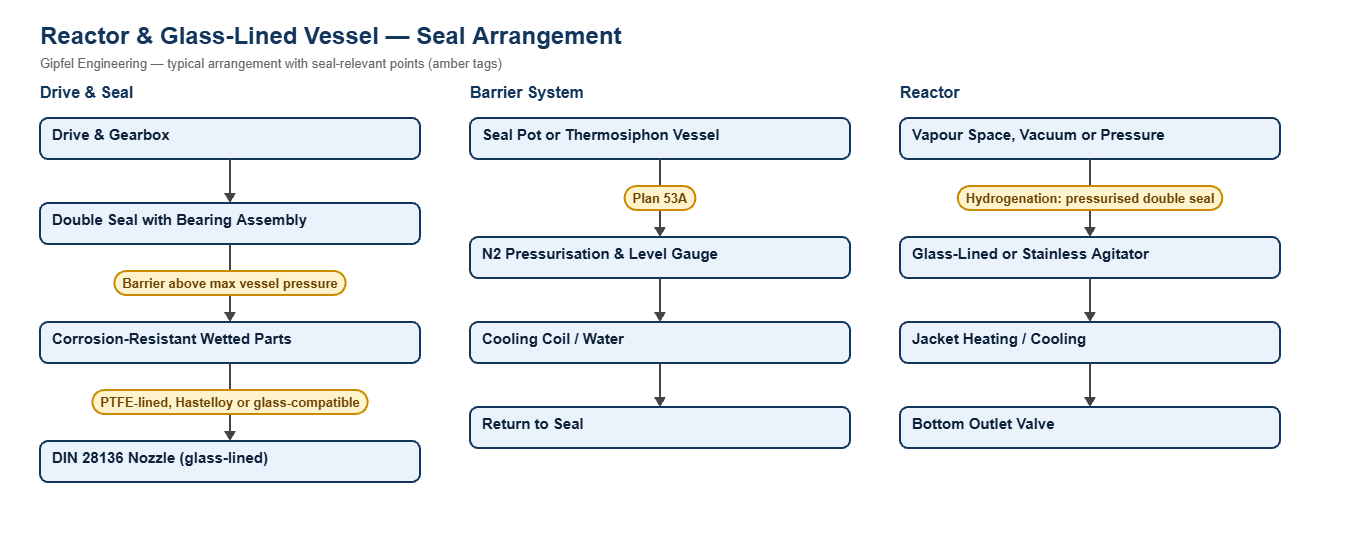
The reactor shaft seal has to contain the product through vacuum distillation, pressure steps and reaction peaks, keep air out under vacuum, and survive the same runout and slow speed as any agitator seal. On glass-lined reactors the seal must also protect the glass: no metal parts that the product can attack, clamping that does not stress the glass-lined nozzle, and connection dimensions to DIN 28136, DIN 28137 and DIN 28159. Almost all reactor duties therefore use a pressurised double seal with a barrier system.
Key Sealing Challenges
- Corrosion: wetted parts are chosen for the product, for example PTFE-lined parts or Hastelloy C on acid duties.
- Pressure swings: barrier pressure must stay at least 1.4 bar above the highest vessel pressure, including reaction peaks, or product will cross the product-side faces.
- Hydrogen: hydrogen escapes through very small gaps and can blister elastomers on rapid venting, so pressurised double seals and suitable elastomers are needed.
- Batch contamination: barrier fluid entering the batch can spoil it. Choose a product-compatible barrier, or a Plan 74 gas barrier seal.
Which mechanical seal suits a glass-lined reactor?
Glass-lined reactors normally use a double seal with bearing assembly or a multi-entry seal system built for glass-lined vessels, with corrosion-resistant wetted parts and DIN 28136 / 28137 / 28159 connection dimensions. Run it on a Plan 53A barrier at least 1.4 bar above maximum vessel pressure, or on Plan 74 nitrogen where barrier liquid must not reach the batch.
Fault Diagnosis Example
Symptom: GLR seal leaks product to atmosphere during the pressure step of each batch, but is dry under vacuum.
  ├── Incorrect Response: "Replace the seal faces every batch."
  ├── Diagnostic Evidence Required:
  │     ├── Log barrier pressure against vessel pressure through a whole batch; does vessel pressure overtake the barrier?
  │     ├── Check the seal pot nitrogen regulator and level.
  │     └── Inspect the product-side faces and wetted parts for chemical attack.
  └── Engineered Solution:
        ├── Set barrier pressure at least 1.4 bar above the highest vessel pressure in the batch.
        ├── Fit low-pressure and low-level alarms on the seal pot.
        └── Confirm wetted-part materials against the product chemistry.
Frequently Asked Questions
Why do glass-lined reactors need special seals?
Glass resists almost every chemical the reactor handles, so the seal must not introduce a less resistant material. Wetted parts must resist the product, and the seal must be clamped without stressing the glass-lined nozzle, whose connection dimensions follow DIN 28136 and DIN 28137.
Is a single seal ever acceptable on a reactor?
Only on non-hazardous, atmospheric duties. Most reactors run under vacuum or pressure with hazardous products, so a pressurised double seal is the normal choice.
How is a hydrogenation reactor seal different?
Hydrogen escapes far more easily than liquids, so the seal is a pressurised double seal with the barrier above maximum hydrogen pressure. Elastomers must resist damage from rapid gas decompression when the reactor is vented.
Related: Agitators · Dryers & ANFD · API & Bulk Drug · Chemical Plants · All reactor solutions.
Request a Seal Selection
Send the reactor and agitator drawings, nozzle standard, shaft size and speed, vessel design pressure and temperature, and the product to info@gipfelengg.com or use our enquiry form. Gipfel Engineering (ISO 9001:2015, NSIC-registered MSME, Mumbai) designs and manufactures mechanical seals, seal support systems and process pumps.
Reactor Duty & Mechanical Seal Selection Matrix
Typical values for selection guidance only. Final selection is made against the reactor and agitator drawings, vessel design pressure, temperature and product.
| Reactor type / duty | Typical equipment | Typical conditions | Seal arrangement | Faces / materials | Barrier / piping plan |
|---|---|---|---|---|---|
| Glass-lined reactor (GLR) — acids, solvents and corrosive intermediates | Glass-lined reactors (DIN 28136 / 28137 / 28159 connections) | Highly corrosive product; glass-lined agitator; vacuum to moderate pressure | Multi-entry single seal system for glass-lined reactors or Double seal with bearing assembly with corrosion-resistant wetted parts | SiC vs carbon or SiC vs SiC; PTFE-lined, Hastelloy C or other wetted parts chosen for the product; FFKM | Plan 53A barrier ≥ 1.4 bar above maximum vessel pressure (Plan 53A) |
| Stainless-steel chemical reactor | Batch and continuous stainless-steel reactors (seals to DIN 28138) | Solvents, intermediates; vacuum distillation and pressure steps | Double seal with bearing assembly | SiC vs carbon; FKM or FFKM (FFKM where amines, ketones or aromatics are present) | Plan 53A barrier above maximum vessel pressure |
| Hydrogenation reactor | Pressure hydrogenators and autoclave-type reactors | Hydrogen under pressure; small molecule escapes easily; rapid venting possible | Double seal with bearing assembly (pressurised double) | SiC vs carbon or SiC vs SiC; elastomers resistant to rapid gas decompression | Pressurised barrier above maximum hydrogen pressure: Plan 53A, or Plan 53B at higher pressures |
| Polymerisation and resin reactor | Resin, polymer and emulsion reactors | Product polymerises or hardens if it reaches the faces | Double seal with bearing assembly | SiC vs SiC; FKM or FFKM | Plan 53A with a barrier fluid compatible with the product; keep barrier pressure above vessel pressure at all times |
| Gas-induction reactor | Hollow-shaft gas-induction reactors and agitators | Seal sees reactor gas pressure in the head space | Double seal with bearing assembly | SiC vs carbon; FKM or FFKM | Plan 53A barrier above gas pressure |
| Reactors where barrier liquid must not enter the product | Pharmaceutical API and fine-chemical reactors | Liquid barrier leakage would contaminate the batch | Double dry-running seal (gas barrier) | Gas-lubricated faces to the seal datasheet; FFKM or FDA-compliant elastomers | Plan 74 nitrogen barrier above vessel pressure |
| Horizontal and photochemical reactors | Special reactor designs | Shaft arrangement varies by design | Engineered to the reactor drawing (on request) | To suit product | To suit duty |
Reviewed by Gipfel Engineering’s technical team.
Technical Information Disclaimer
The information on this page, including process descriptions, flow diagrams, operating ranges, seal arrangements, materials and piping plans, is general technical guidance for information only. Values shown are typical industry ranges, not guaranteed ratings or specifications of any Gipfel Engineering product. Each application differs. Seal selection, material compatibility, installation and operation must be verified by qualified personnel against the specific equipment data sheet, process conditions, applicable codes and the pump manufacturer’s instructions. A binding recommendation is given only in a written quotation or technical offer from Gipfel Engineering.
References to standards (such as API 682, ISO 21049, ISO 3069, FDA 21 CFR 177.2600 and NACE MR0175 / ISO 15156) describe common industry practice. They do not mean that any product is certified, qualified or approved to that standard unless this is confirmed in writing for a specific order. Third-party company and product names, including “equivalent to” references, are used for identification only and remain the trademarks of their owners. No affiliation, endorsement or OEM approval is implied.
Compliance with safety, hazardous-area, environmental and statutory requirements at the user’s site remains the responsibility of the plant owner or operator. To the extent permitted by law, Gipfel Engineering accepts no liability for loss or damage arising from reliance on this general information without a confirmed written recommendation. Content may change without notice.