
Upstream Oil & Gas Production
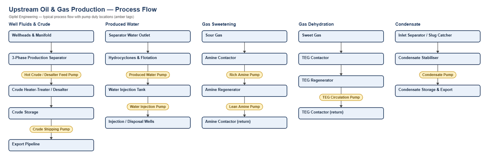
Process Overview
Upstream Oil & Gas Production — Process Overview
Upstream production separates well fluids into crude oil, gas and produced water, then treats each stream for export or reinjection. Crude is stabilised, dehydrated and desalted; gas is sweetened with amine, dried with triethylene glycol (TEG) and stripped of condensate; produced water is de-oiled and reinjected or disposed of. Many streams are sour (containing H₂S), sandy or at high pressure.
For crude and product pipelines, terminals and LPG see Pipelines, Terminals & LPG; for refinery units see Refinery.
Key Sealing Challenges
- Sour service: H₂S calls for materials qualified to NACE MR0175 / ISO 15156 and elastomers such as FEPM (Aflas) or FFKM.
- Sand and solids: produced water carries sand that erodes faces; API Plan 31 cyclone separators deliver clean flush liquid.
- High pressure: water injection pumps discharge at 100–250 bar. The seal is sized for seal-chamber (suction / balance-line) pressure.
- Emissions and safety: volatile or toxic fluids use Arrangement 2 tandem seals with an API Plan 52 buffer vented to flare.
What mechanical seal is used on produced water pumps?
Produced water pumps typically use a balanced cartridge seal with duplex or super duplex metal parts and silicon carbide vs. silicon carbide faces, with FKM or FEPM (Aflas) elastomers for H₂S. Where the water carries sand, an API Plan 31 cyclone separator removes solids from the flush before it reaches the seal faces.
Root-Cause Failure Analysis — Field Example
Symptom: Produced water pump seal fails in 4–8 weeks; faces grooved, flush line partly blocked.
  ├── Incorrect Response: "Fit a harder face material."
  ├── Diagnostic Evidence Required:
  │     ├── Is the water carrying sand, and is the seal on a plain Plan 11 flush feeding solids straight to the faces?
  │     ├── Check chloride and H₂S levels against the seal metal parts and elastomers.
  │     └── Inspect the flush orifice and line for sand packing.
  └── Engineered Solution:
        ├── Change to API Plan 31: a cyclone separator returns solids to suction and sends clean liquid to the seal.
        ├── SiC vs SiC faces with duplex or super duplex metal parts.
        └── FEPM (Aflas) or FKM elastomers selected for the H₂S level.
Frequently Asked Questions
What is the difference between API Plan 31 and Plan 32?
Plan 31 cleans the pumped fluid with a cyclone separator and sends it to the seal, keeping process chemistry unchanged. Plan 32 injects clean liquid from an outside source, which dilutes the process stream. Plan 31 suits sandy produced water; Plan 32 is used where solids are too fine or too heavy for a cyclone.
Which elastomers are used in sour (H₂S) service?
FEPM (Aflas) and FFKM resist H₂S and amine corrosion inhibitors better than standard FKM. Metal parts should meet NACE MR0175 / ISO 15156 for the H₂S partial pressure and temperature.
Related: Pipelines, Terminals & LPG · Refinery · Biofuels · Marine.
Request a Seal Selection
Send your pump make and model, fluid, temperature, pressure, shaft size and speed to info@gipfelengg.com or use our enquiry form. Gipfel Engineering (ISO 9001:2015, NSIC-registered MSME, Mumbai) designs and manufactures mechanical seals, seal support systems and process pumps.
Equipment solutions: Split-Case Pumps · Boiler Feed & Multistage Pumps · Compressors & Bearing Chambers.
Pump Duty & Mechanical Seal Selection Matrix
Typical values for selection guidance only. Final selection is made against the customer duty sheet.
| Pump duty | Fluid | Typical temp. | Typical pressure (bar) | Seal arrangement | Faces / elastomer | API piping plan |
|---|---|---|---|---|---|---|
| Crude Shipping / Export Pump | Stabilised crude, may contain H₂S | 40–80 °C | Discharge to pipeline pressure. The seal sees seal-chamber pressure — confirm per pump | API 682 cartridge seal (Arrangement 1); Tandem double cartridge (Arrangement 2) for sour or emission-controlled duty | SiC vs carbon / FKM, or FEPM (Aflas) in sour service | API Plan 11; Plan 11 + Plan 52 for Arrangement 2 |
| Hot Crude / Desalter Feed Pump | Crude oil with wash water | 120–145 °C | 15–25 bar | API 682 cartridge seal (Arrangement 1) | SiC vs carbon / FEPM (Aflas) or FKM | API Plan 23 (or Plan 21) |
| Produced Water Pump | Brine with oil traces, sand and possible H₂S | 40–90 °C | 3–15 bar | Balanced multi-spring cartridge with duplex or super duplex metal parts | SiC vs SiC / FKM or FEPM | API Plan 31 (cyclone separator) where sand is present; Plan 11 for clean water |
| Water Injection Pump | Treated seawater or produced water | Ambient–60 °C | Discharge 100–250 bar. The seal sees suction / balance-line pressure — confirm per pump | High-pressure balanced cartridge, stationary springs (catalogue ref. HP760) with super duplex metal parts | SiC vs SiC / FKM or EPDM | API Plan 11; Plan 31 where fine solids are present |
| Rich Amine Pump | Rich MDEA loaded with H₂S and CO₂ | 50–80 °C | Seal-chamber pressure — confirm per pump | Tandem double cartridge (Arrangement 2) | SiC vs SiC / FFKM (amines attack FKM) | API Plan 11 + Plan 52 (buffer vented to flare) |
| Lean Amine Pump | Lean MDEA with hydrocarbon traces | 40–60 °C | Discharge to contactor pressure; the seal sees suction pressure — confirm per pump | Balanced multi-spring cartridge | SiC vs SiC / FFKM | API Plan 11 |
| TEG Circulation Pump (centrifugal units) | Lean triethylene glycol | 60–90 °C | Discharge to contactor pressure; many units use reciprocating pumps instead | Balanced multi-spring cartridge | SiC vs carbon / FKM | API Plan 11 |
| Condensate / NGL Pump | Stabilised condensate, high vapour pressure | 20–60 °C | 5–30 bar; keep seal-chamber pressure margin above vapour pressure | Tandem double cartridge (Arrangement 2) | Carbon vs SiC / FKM | API Plan 11 + Plan 52 (buffer vapour to flare or recovery) |
| Closed / Open Drain Pump (vertical) | Oily drains | Ambient | 2–6 bar | Balanced multi-spring cartridge | SiC vs SiC / FKM | API Plan 13 (vents the seal chamber of vertical pumps) |
Reviewed by Gipfel Engineering’s technical team.
Technical Information Disclaimer
The information on this page, including process descriptions, flow diagrams, operating ranges, seal arrangements, materials and piping plans, is general technical guidance for information only. Values shown are typical industry ranges, not guaranteed ratings or specifications of any Gipfel Engineering product. Each application differs. Seal selection, material compatibility, installation and operation must be verified by qualified personnel against the specific equipment data sheet, process conditions, applicable codes and the pump manufacturer’s instructions. A binding recommendation is given only in a written quotation or technical offer from Gipfel Engineering.
References to standards (such as API 682, ISO 21049, ISO 3069, FDA 21 CFR 177.2600 and NACE MR0175 / ISO 15156) describe common industry practice. They do not mean that any product is certified, qualified or approved to that standard unless this is confirmed in writing for a specific order. Third-party company and product names, including “equivalent to” references, are used for identification only and remain the trademarks of their owners. No affiliation, endorsement or OEM approval is implied.
Compliance with safety, hazardous-area, environmental and statutory requirements at the user’s site remains the responsibility of the plant owner or operator. To the extent permitted by law, Gipfel Engineering accepts no liability for loss or damage arising from reliance on this general information without a confirmed written recommendation. Content may change without notice.