
Multistage High-Pressure & Boiler Feed Pumps
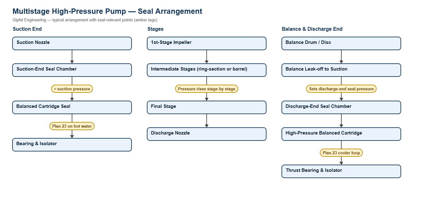
Process Overview
Multistage High-Pressure & Boiler Feed Pumps — Sealing Overview
Multistage pumps build pressure through several impellers in series. Horizontal designs include axially split (API 610 BB3), ring-section (BB4) and double-casing barrel (BB5) pumps used for boiler feed, pipeline, water injection and high-pressure process duty. Vertical in-line multistage pumps serve pressure boosting, RO feed and small boiler feed.
The seal does not normally see discharge pressure. On horizontal pumps the suction-end seal sits at about suction pressure, and the discharge-end seal sits behind a balance drum or disc whose leak-off is piped back to suction, so it too runs close to suction pressure. Select the seal for that seal-chamber pressure and confirm it from the pump maker. Vertical in-line pumps are the exception: the seal is in the top chamber at or near discharge pressure.
Key Sealing Challenges
- Hot feedwater: feedwater has little lubricity and flashes easily. API Plan 23 uses a pumping ring to circulate seal-chamber water through a cooler, so only the small seal-chamber volume is cooled rather than a continuous flush.
- Speed and face loading: high-speed boiler feed pumps raise face surface speed; balanced seals with stationary springs keep face loading and heat generation under control.
- Thermal transients: starts, trips and warm-up cycles thermally shock faces and elastomers; SiC vs carbon faces tolerate this better than hard-vs-hard pairs.
- Balance-line problems: a worn balance drum raises leak-off flow and pressure, which raises the discharge-end seal-chamber pressure.
Which mechanical seal suits a multistage boiler feed pump?
Boiler feed pumps typically use a balanced cartridge seal with stationary springs at each end on an API Plan 23 cooling loop, with SiC vs carbon faces and EPDM or FEPM elastomers. Size the seal for seal-chamber pressure, which is close to suction or balance leak-off pressure, not pump discharge.
Fault Diagnosis Example
Symptom: Discharge-end seal on a boiler feed pump runs hot and fails; the suction-end seal is healthy.
  ├── Incorrect Response: "Fit a seal rated for full discharge pressure."
  ├── Diagnostic Evidence Required:
  │     ├── Measure balance leak-off pressure and flow; have they risen since the last overhaul?
  │     ├── Check the Plan 23 loop: was it vented at its high point, and is the cooler fouled?
  │     └── Inspect faces for heat checking and the elastomers for hardening.
  └── Engineered Solution:
        ├── Restore balance drum clearances to bring seal-chamber pressure back to design.
        ├── Vent and clean the Plan 23 loop; keep cooling water on during standby.
        └── Use SiC vs carbon faces with peroxide-cured EPDM or FEPM.
Frequently Asked Questions
Why does a boiler feed pump seal not need a discharge pressure rating?
Both seals sit in chambers connected to suction, one directly and one through the balance drum leak-off. Their pressure is close to suction pressure, which is far below discharge. The seal still needs the right rating for that pressure, temperature and speed.
Why is Plan 23 preferred over Plan 21 on hot water?
Plan 21 cools a continuous flush taken from discharge, which wastes heat and needs a large cooler. Plan 23 recirculates only the seal-chamber water through the cooler, so the cooler duty is much smaller and the seal runs cooler.
What is the main cause of seal failure on vertical multistage pumps?
Dry running, usually because the top chamber was not vented before start-up or the pump ran with a closed suction valve. The faces can be damaged within seconds. Vent the pump before every start after draining.
Related: Coal-Fired Thermal Power · Co-Generation & Biomass · Desalination & RO · Overhung Pumps · All process pump solutions.
Request a Seal Selection
Send your pump make and model, fluid, temperature, pressure, shaft size and speed to info@gipfelengg.com or use our enquiry form. Gipfel Engineering (ISO 9001:2015, NSIC-registered MSME, Mumbai) designs and manufactures mechanical seals, seal support systems and process pumps.
Multistage Pump Duty & Mechanical Seal Selection Matrix
Typical values for selection guidance only. Final selection is made against the pump data sheet and the measured or specified seal-chamber pressure.
| Pump type / duty | Typical makes & models | Typical conditions | Seal arrangement | Faces / elastomer | API piping plan |
|---|---|---|---|---|---|
| Ring-section boiler feed pump (BB4) | KSB HGC; Sulzer MBN; Akay BB4 | Deaerated feedwater 105–180 °C; seal chambers at suction or balance leak-off pressure, not discharge | High-pressure balanced cartridge, stationary springs (catalogue ref. HP760) or Balanced multi-spring cartridge seal (by seal-chamber pressure) | SiC vs carbon; peroxide-cured EPDM or FEPM | Plan 23 cooling loop (Plan 23) |
| Double-casing barrel pump (BB5) | Akay BB5 (model to confirm) | HP boiler feed and high-pressure process duty; seal-chamber pressure to the pump datasheet | High-pressure balanced cartridge, stationary springs (catalogue ref. HP760) on water; Double cartridge seal, back-to-back (pressurised) on hydrocarbons | SiC vs carbon; EPDM / FEPM (water), FKM or FFKM (hydrocarbons) | Plan 23 on hot water; Plan 53B on hazardous hydrocarbons |
| Axially split multistage pump (BB3) | Akay BB3 (model to confirm) | Water supply, mine dewatering and pipeline duty | Balanced multi-spring cartridge seal | SiC vs carbon; SiC vs SiC where solids are present; EPDM or FKM | Plan 11; Plan 32 on dirty water |
| Horizontal ring-section multistage water pump | KSB WKLn; Lowara e-HM; CRI MH | Boiler feed for small boilers, pressure boosting, RO feed | Balanced multi-spring cartridge seal or Wave-spring semi-cartridge seal | Carbon vs SiC; EPDM | Plan 11; Plan 23 above about 80 °C |
| Vertical in-line multistage pump | Grundfos CR; CNP CDL; CRI MV | Seal sits in the top chamber at or near discharge pressure, so its pressure rating must cover discharge | Single-spring cartridge seal for Grundfos-type pumps or a cartridge seal to the maker’s dimensions | SiC vs SiC or carbon vs SiC; EPDM (water) or FKM | Internal recirculation; vent the top chamber before start-up |
Reviewed by Gipfel Engineering’s technical team.
Technical Information Disclaimer
The information on this page, including process descriptions, flow diagrams, operating ranges, seal arrangements, materials and piping plans, is general technical guidance for information only. Values shown are typical industry ranges, not guaranteed ratings or specifications of any Gipfel Engineering product. Each application differs. Seal selection, material compatibility, installation and operation must be verified by qualified personnel against the specific equipment data sheet, process conditions, applicable codes and the pump manufacturer’s instructions. A binding recommendation is given only in a written quotation or technical offer from Gipfel Engineering.
References to standards (such as API 682, ISO 21049, ISO 3069, FDA 21 CFR 177.2600 and NACE MR0175 / ISO 15156) describe common industry practice. They do not mean that any product is certified, qualified or approved to that standard unless this is confirmed in writing for a specific order. Third-party company and product names, including “equivalent to” references, are used for identification only and remain the trademarks of their owners. No affiliation, endorsement or OEM approval is implied.
Compliance with safety, hazardous-area, environmental and statutory requirements at the user’s site remains the responsibility of the plant owner or operator. To the extent permitted by law, Gipfel Engineering accepts no liability for loss or damage arising from reliance on this general information without a confirmed written recommendation. Content may change without notice.