
Top, Side & Bottom-Entry Agitators
Process Overview
Top, Side & Bottom-Entry Agitators — Sealing Overview
Agitators mix, suspend, disperse and transfer heat in vessels ranging from small pharmaceutical reactors to large storage tanks. They enter the vessel from the top, side or bottom. Top-entry agitators are the most common; bottom-entry designs suit vessels where the head must stay free; side-entry agitators serve large storage tanks and pulp chests. Agitated Nutsche filters and gas-induction agitators are specialised top-entry designs.
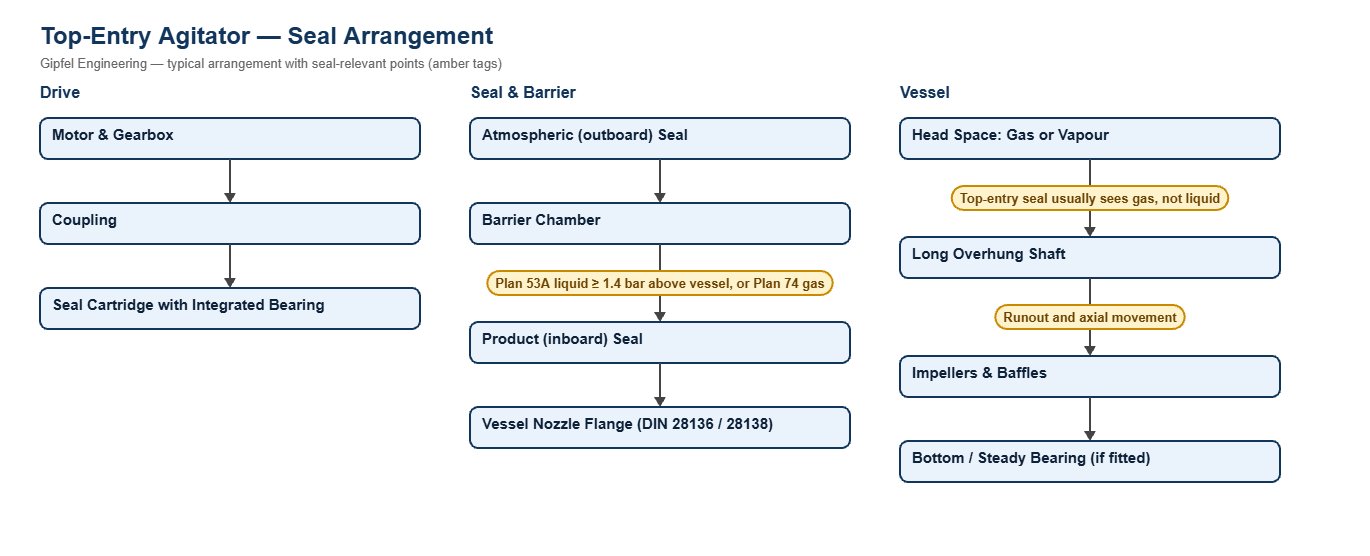
An agitator seal works very differently from a pump seal. Shafts are long and slow, typically tens to a few hundred rpm, with impellers far from the nearest bearing, so radial runout and axial movement at the seal are much larger than on a pump. A top-entry seal usually sees the gas or vapour in the vessel head space rather than liquid, so it must either run dry or be supplied with a barrier. Agitator mechanical seals are commonly built to DIN 28138; on glass-lined vessels the connection, flange and shaft-end dimensions follow DIN 28136, DIN 28137 and DIN 28159.
Key Sealing Challenges
- Runout and axial movement: a cartridge with an integrated bearing holds the faces square to the shaft and protects them from gearbox and shaft movement.
- Dry gas at the faces: top-entry seals rarely see liquid. Use a dry-running seal on harmless duties, or a double seal with a liquid or gas barrier.
- Pressure and vacuum: double seals keep a barrier above vessel pressure, so product cannot escape under pressure and air cannot enter under vacuum.
- Contamination: where a barrier liquid must never reach the batch, a gas-lubricated double seal on Plan 74 is used.
Which mechanical seal suits a top-entry agitator?
On non-hazardous atmospheric vessels, a single dry-running seal with integrated bearing. On toxic, flammable, pressure or vacuum duty, a double seal with bearing assembly on a Plan 53A barrier at least 1.4 bar above maximum vessel pressure. Where barrier liquid must not reach the product, a gas-lubricated double seal on Plan 74.
Fault Diagnosis Example
Symptom: Barrier pot on a reactor agitator seal loses level quickly and barrier oil is found in the batch.
  ├── Incorrect Response: "Top up the pot more often."
  ├── Diagnostic Evidence Required:
  │     ├── Is barrier pressure at least 1.4 bar above the highest vessel pressure, including during reaction peaks?
  │     ├── Measure shaft runout at the seal; check the gearbox output bearings.
  │     └── Inspect the product-side faces for chipping from runout or solids.
  └── Engineered Solution:
        ├── Correct the barrier pressure setting and alarm on low pressure and low level.
        ├── Use a seal cartridge with an integrated bearing to control runout.
        └── Where barrier liquid must never enter the batch, change to a Plan 74 gas barrier seal.
Frequently Asked Questions
Can a pump seal be used on an agitator?
Not usually. Pump seals are designed for small runout and a liquid-filled chamber. Agitators have far larger shaft movement and often a gas-filled head space, so they need seals designed for that, usually with an integrated bearing.
What barrier pressure does a double agitator seal need?
At least 1.4 bar above the highest pressure the vessel reaches, including reaction peaks, so leakage across the product-side faces is always barrier into vessel and never product out. Under vacuum, the barrier also stops air entering the vessel.
Do side-entry agitators need the tank emptied to change the seal?
Most side-entry agitators have a shaft shut-off device that seals the shaft opening while the seal is changed, so the tank can stay full. Confirm the procedure with the agitator maker.
Related: Chemical & Glass-Lined Reactors · Dryers & ANFD · Fermenters & Bioreactors · API & Bulk Drug · All agitator solutions.
Request a Seal Selection
Send the agitator and vessel drawings, shaft size and speed, vessel design pressure and temperature, and the product to info@gipfelengg.com or use our enquiry form. Gipfel Engineering (ISO 9001:2015, NSIC-registered MSME, Mumbai) designs and manufactures mechanical seals, seal support systems and process pumps.
Agitator Duty & Mechanical Seal Selection Matrix
Typical values for selection guidance only. Final selection is made against the vessel and agitator drawings, vessel design pressure and temperature.
| Agitator type / duty | Typical equipment | Typical conditions | Seal arrangement | Faces / elastomer | Barrier / piping plan |
|---|---|---|---|---|---|
| Top-entry agitator — non-hazardous product, atmospheric or low pressure | Mixing, storage and dissolving vessels | Seal sees head-space gas or vapour; low speed; large runout | Single dry-running agitator seal with bearing support or Single dry mechanical seal | Dry-running carbon vs SiC; FKM or EPDM | None needed (dry running); add a quench only if vapour condenses and crystallises |
| Top-entry agitator — toxic, flammable, pressure or vacuum duty | Chemical and pharmaceutical process vessels | Vessel pressure or vacuum; emissions must be contained | Double seal with bearing assembly | SiC vs carbon (product side); FKM or FFKM | Plan 53A liquid barrier ≥ 1.4 bar above maximum vessel pressure, with seal pot |
| Top-entry agitator — barrier liquid must not reach the product | Pharmaceutical, fine-chemical and food vessels | A liquid barrier leak would contaminate the batch | Double dry-running seal (gas barrier) | Gas-lubricated faces to the seal datasheet; FDA-compliant or FFKM elastomers | Plan 74 dry nitrogen or clean-air barrier above vessel pressure |
| Bottom-entry agitator | Bottom-driven mixers and homogenising vessels | Seal is submerged: sees vessel pressure plus liquid head; solids can settle on the seal | Double seal with bearing assembly | SiC vs SiC (product side); FKM, EPDM or FFKM | Plan 53A barrier above vessel pressure plus liquid head |
| Side-entry agitator — storage tanks, pulp and stock chests | Crude, product and stock tanks | Seal is submerged at tank head; most designs have a shaft shut-off so the seal can be changed with the tank full (confirm with the agitator maker) | Balanced multi-spring cartridge seal or Slurry cartridge seal, external springs (catalogue ref. HS860) | SiC vs SiC; EPDM or FKM | Plan 32 clean flush on stock or slurry; Plan 62 quench where product hardens |
Reviewed by Gipfel Engineering’s technical team.
Technical Information Disclaimer
The information on this page, including process descriptions, flow diagrams, operating ranges, seal arrangements, materials and piping plans, is general technical guidance for information only. Values shown are typical industry ranges, not guaranteed ratings or specifications of any Gipfel Engineering product. Each application differs. Seal selection, material compatibility, installation and operation must be verified by qualified personnel against the specific equipment data sheet, process conditions, applicable codes and the pump manufacturer’s instructions. A binding recommendation is given only in a written quotation or technical offer from Gipfel Engineering.
References to standards (such as API 682, ISO 21049, ISO 3069, FDA 21 CFR 177.2600 and NACE MR0175 / ISO 15156) describe common industry practice. They do not mean that any product is certified, qualified or approved to that standard unless this is confirmed in writing for a specific order. Third-party company and product names, including “equivalent to” references, are used for identification only and remain the trademarks of their owners. No affiliation, endorsement or OEM approval is implied.
Compliance with safety, hazardous-area, environmental and statutory requirements at the user’s site remains the responsibility of the plant owner or operator. To the extent permitted by law, Gipfel Engineering accepts no liability for loss or damage arising from reliance on this general information without a confirmed written recommendation. Content may change without notice.