
Industrial Turbines
Process Overview
Industrial Turbines — Sealing Overview
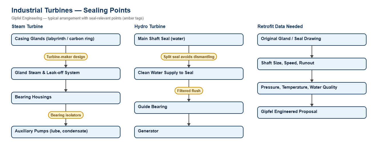
Industrial turbines include mechanical-drive and generator steam turbines in power, sugar, distillery and process plants, Francis and Kaplan hydro turbines, and gas-induction turbines and expanders. Each has several sealing points: the casing glands where the shaft leaves the steam or water space, the bearing housings, and the auxiliary pumps that serve the turbine.
Steam turbine casing glands are labyrinth or carbon-ring designs specified by the turbine maker, supported by a gland steam and leak-off system; they are not mechanical seals and are retrofitted only from the original drawings. The commonest reliability gain on steam turbines is at the bearing housings, where steam and condensate get into the oil past worn lip seals. On hydro turbines, the main shaft seal sits in water, and a split mechanical seal can be fitted without dismantling the turbine on suitable shaft sizes.
Key Sealing Challenges
- Water in bearing oil: gland leakage condenses and enters the bearings. Non-contacting bearing isolators keep it out.
- Downtime: dismantling a hydro turbine to change a seal is very costly; split seals avoid it where the duty allows.
- Maker-specific designs: glands and shaft seals differ between turbine makers, so every retrofit starts from the drawing and operating data.
- Auxiliary pumps: boiler feed and condensate pump seals are often the turbine island’s weakest point; see the multistage pump page.
Which seals does an industrial steam turbine need?
The casing glands are labyrinth or carbon-ring designs from the turbine maker, retrofitted only from the original drawing. The bearing housings benefit from non-contacting bearing isolators that keep steam and water out of the oil. Hydro turbines can use a split mechanical seal on the main shaft where the size and duty suit.
Fault Diagnosis Example
Symptom: Steam turbine bearing oil turns milky and bearings wear early.
  ├── Incorrect Response: "Change the oil more often."
  ├── Diagnostic Evidence Required:
  │     ├── Is gland steam leaking along the shaft towards the bearing housings?
  │     ├── Is the gland leak-off and gland condenser working?
  │     └── What seals the bearing housings: worn lip seals?
  └── Engineered Solution:
        ├── Restore gland leak-off and gland condenser vacuum.
        ├── Fit non-contacting bearing isolators on the bearing housings.
        └── Monitor water content in the oil after the change.
Frequently Asked Questions
Can a steam turbine gland be replaced with a mechanical seal?
Generally no. Steam turbine glands are labyrinth or carbon-ring designs matched to the turbine. Gipfel works from the original drawing on gland upgrades and supplies bearing isolators and auxiliary pump seals.
What information is needed for a hydro turbine shaft seal?
Shaft diameter and speed, shaft runout, water head at the seal, water quality and the existing seal or gland drawing. A split seal is considered first because it avoids dismantling.
Related: Boiler Feed Pumps · Coal-Fired Thermal Power · Co-Generation & Biomass · All turbine solutions.
Request a Seal Selection
Send the turbine make and model, the gland or seal drawing, shaft size and speed and operating conditions to info@gipfelengg.com or use our enquiry form. Gipfel Engineering (ISO 9001:2015, NSIC-registered MSME, Mumbai) designs and manufactures mechanical seals, seal support systems and process pumps.
Turbine Sealing Points & Seal Selection Matrix
Typical values for selection guidance only. Turbine gland and shaft-seal designs are specific to each turbine maker; Gipfel engineers each retrofit from the original drawings and operating data.
| Turbine / sealing point | Typical equipment | Typical conditions | Seal arrangement | Seal materials | Supply / buffer |
|---|---|---|---|---|---|
| Steam turbine casing glands | Mechanical-drive and generator steam turbines | Steam at the shaft passage; gland steam and leak-off system | Labyrinth or carbon-ring glands are the turbine maker’s design; replacement or upgrade engineered from the original drawing (on request) | Carbon rings or metallic labyrinths | Gland steam and leak-off per the turbine maker |
| Steam turbine bearing housings | All steam turbines | Oil contamination from steam leakage and condensate | Split bearing isolator | Non-contacting labyrinth design | Keeps water and steam out of the bearing oil |
| Hydro turbine main shaft seal | Francis and Kaplan hydro turbines (size to confirm) | Water at the shaft passage; dismantling the turbine to change a seal is very costly | Split mechanical seal on suitable shaft sizes, or a seal engineered from the drawing (on request) | Carbon or SiC vs SiC; EPDM | Filtered clean-water supply to the seal |
| Gas-induction and expander turbines | Gas-induction turbines and expanders | Process gas at the shaft passage | Gas-lubricated (dry gas) seal (on suitable designs) | Gas-lubricated faces to the seal datasheet | Nitrogen buffer to the turbine maker’s design |
| Turbine auxiliary pumps | Boiler feed, condensate and lube-oil pumps | See the pump pages for each duty | High-pressure balanced cartridge (catalogue ref. HP760) on boiler feed pumps | SiC vs carbon; EPDM or FEPM | Plan 23 on hot water |
Reviewed by Gipfel Engineering’s technical team.
Technical Information Disclaimer
The information on this page, including process descriptions, flow diagrams, operating ranges, seal arrangements, materials and piping plans, is general technical guidance for information only. Values shown are typical industry ranges, not guaranteed ratings or specifications of any Gipfel Engineering product. Each application differs. Seal selection, material compatibility, installation and operation must be verified by qualified personnel against the specific equipment data sheet, process conditions, applicable codes and the pump manufacturer’s instructions. A binding recommendation is given only in a written quotation or technical offer from Gipfel Engineering.
References to standards (such as API 682, ISO 21049, ISO 3069, FDA 21 CFR 177.2600 and NACE MR0175 / ISO 15156) describe common industry practice. They do not mean that any product is certified, qualified or approved to that standard unless this is confirmed in writing for a specific order. Third-party company and product names, including “equivalent to” references, are used for identification only and remain the trademarks of their owners. No affiliation, endorsement or OEM approval is implied.
Compliance with safety, hazardous-area, environmental and statutory requirements at the user’s site remains the responsibility of the plant owner or operator. To the extent permitted by law, Gipfel Engineering accepts no liability for loss or damage arising from reliance on this general information without a confirmed written recommendation. Content may change without notice.